Mechanical finger and manipulator including same

A technology of mechanical fingers and manipulators, which is applied in the field of automation equipment, can solve problems such as the easy shaking of the clamping section, the inability to grasp special-shaped workpieces, and the unstable grasping of the manipulator, so as to achieve stable gripping, strong versatility, and stable gripping and the effect of grabbing

Pending Publication Date: 2019-01-15
顺诠达(重庆)电子有限公司
View PDF1 Cites 5 Cited by
  • Summary
  • Abstract
  • Description
  • Claims
  • Application Information

AI Technical Summary

Problems solved by technology

[0003] Most of the current manipulators use a single-joint clamping method. This kind of manipulator has a simple structure and low processing cost. However, due to the small degree of freedom of the manipulator fingers, the manipulator can only grab specific types of workpieces. Usually, the manipulator and the gripper One-to-one setting of workpieces, unable to grab special-shaped workpieces
In the prior art, there have been technologies disclosed in Chinese patent CN106426255A, and prior art such as Figure 12 As shown, the mechanical finger is a multi-joint design, the first joint 110 and the second joint 111 are hinged to each other to form a power transmission chain, the third joint 112 and the fourth joint 113 are hinged to each other to form a clamping part, the third joint 112 and the fourth joint The joint 113 forms two clamping sections of the clamping part, which can realize the clamping of special-shaped workpieces; but in the clamping process, only a single guide force transmission chain is used to control the grasping of the workpiece by the clamping part, and the workpiece is When grasping, the two clamping sections in the clamping part are prone to shake, causing the manipulator to grasp unstable

Method used


Image

  • Mechanical finger and manipulator including same
  • Mechanical finger and manipulator including same
  • Mechanical finger and manipulator including same

Examples


Embodiment 1

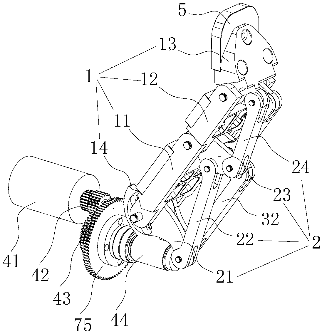
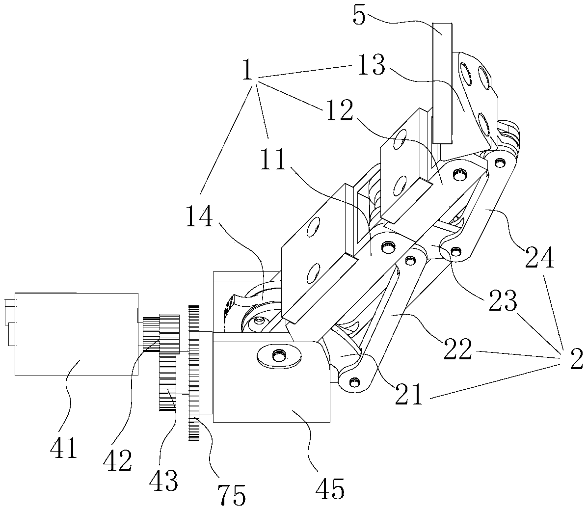
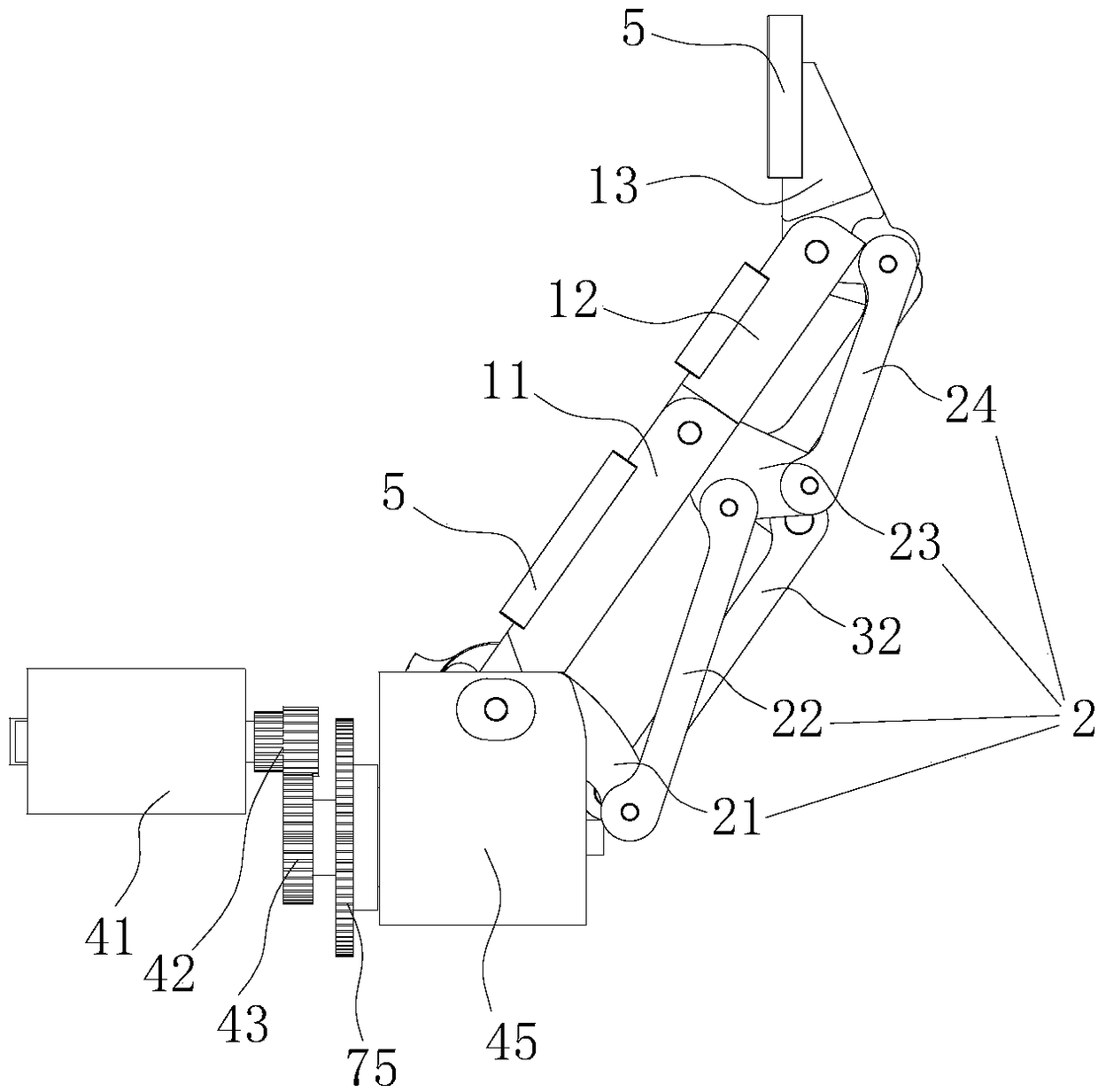
[0039] A mechanical finger, such as Figure 1 to 5 As shown, it includes a knuckle group 1, a guide traction chain 2 that drives the knuckle group 1 to bend, and a self-locking traction chain 3 that drives the knuckle group 1 to bend and self-lock. It also includes a driving guide traction chain 2 and a self-locking chain. The grabbing drive mechanism 4 that locks the traction chain 3 is bent, and the guiding traction chain 2 and the self-locking traction chain 3 are hingedly arranged on one side of the knuckle group 1.

[0040] The implementation of the robotic finger will now be described. The crawl status is like Picture 10 As shown, during use, both the guiding traction chain 2 and the self-locking traction chain 3 are driven by the grabbing drive mechanism 4, and then the knuckle group 1 is turned over under the driving of the guiding traction chain 2 and the self-locking traction chain 3. At this time, the guiding traction chain 2 plays the role of power transmission; when...

Embodiment 2

[0053] A manipulator includes the mechanical finger as described in embodiment 1. It should be understood that the number of manipulator fingers of the manipulator can be set to one or more to achieve envelope grabbing of the special-shaped workpiece. Further, there are three mechanical fingers. It should be noted that the three mechanical fingers can be arranged on the same side, centripetally, and on both sides, etc. The same side setting can realize the envelope capture of the workpiece, and the centripetal setting can realize the alignment. For the clamping action of the workpiece, the two sides can realize the envelope grabbing and clamping action of the workpiece at the same time, and the implementation effect is better.

[0054] Further, such as Figure 6 to 8 As shown, the manipulator also includes a fixing base 6 for fixing the three mechanical fingers. The three mechanical fingers are divided into two left fingers 91 located on one side of the fixing base 6 and anothe...


PUM


Abstract

The invention relates to the technical field of automation equipment, and aims at providing a mechanical finger and a manipulator including the same. The mechanical finger in the technical scheme comprises a finger joint group, a force guiding traction chain driving the finger joint group to bend, a self-locking traction chain driving the finger joint group to bend and self lock, and a grasping driving mechanism driving the force guiding traction chain and the self-locking traction chain to bend. The manipulator comprises three mechanical fingers and a fixing seat, wherein the three mechanicalfingers are two left fingers located at one side of the fixing seat and a right finger located at the other side of the fixing seat; three grasping driving mechanisms in the three mechanical fingersare two first grasping driving mechanisms located at one side of the fixing seat and a second grasping driving mechanism located at the other side of the fixing seat; and the fixing seat is fixedly connected with first driving devices in the first grasping driving mechanisms and the second grasping driving mechanism. Thus, a workpiece can be stably grasped.

Description

Technical field [0001] The invention relates to the technical field of automation equipment, in particular to a mechanical finger and a manipulator. Background technique [0002] A manipulator is an automatic operating device that can imitate certain motion functions of human hands and arms to grasp, transport objects or operate tools according to a fixed program. Because it can replace human labor to achieve mechanization and automation of production, it can Operating in a harmful environment to protect personal safety, it is widely used in the field of automation equipment technology. [0003] Most of the current manipulators adopt a single-joint clamping method. This manipulator has a simple structure and low processing cost. However, due to the few degrees of freedom of the manipulator fingers, the manipulator often can only grab specific types of workpieces. The workpieces are set one to one, and special-shaped workpieces cannot be grasped. In the prior art, the technology d...

Claims


Application Information

Patent Timeline
Patent Type & Authority Applications(China)
IPC IPC(8): B25J15/00B25J15/02B25J15/10
CPCB25J15/0009B25J15/0213B25J15/10
Inventor 姜三肖义斌季全军
Owner 顺诠达(重庆)电子有限公司
Why Eureka
Try Eureka