Cutting device for excess materials of plastic products

A technology of cutting device and plastic products, applied in metal processing and other directions, can solve the problems of unfavorable collection of waste and waste of labor, and achieve the effect of good continuity and reduced purchase cost.

Inactive Publication Date: 2019-01-15
中山市坤源包装材料有限公司
View PDF6 Cites 8 Cited by
  • Summary
  • Abstract
  • Description
  • Claims
  • Application Information

AI Technical Summary

Problems solved by technology

[0004] The purpose of the present invention is to provide a cutting device for the remaining plastic products, which can effectively solve the problems of labor-intensive and unfavorable for collecting waste in the processing method of manual cutting in the prior art; The upper feeding table and the lower feeding table, the upper feeding table and the lower feeding table cooperate to convey the plastic pipes to be processed, and the distance between the upper feeding table and the lower feeding table can be adjusted through the vertical adjustment frame, which is convenient for different Size of plastic pipe used

Method used


Image

  • Cutting device for excess materials of plastic products
  • Cutting device for excess materials of plastic products
  • Cutting device for excess materials of plastic products

Examples


specific Embodiment approach 1

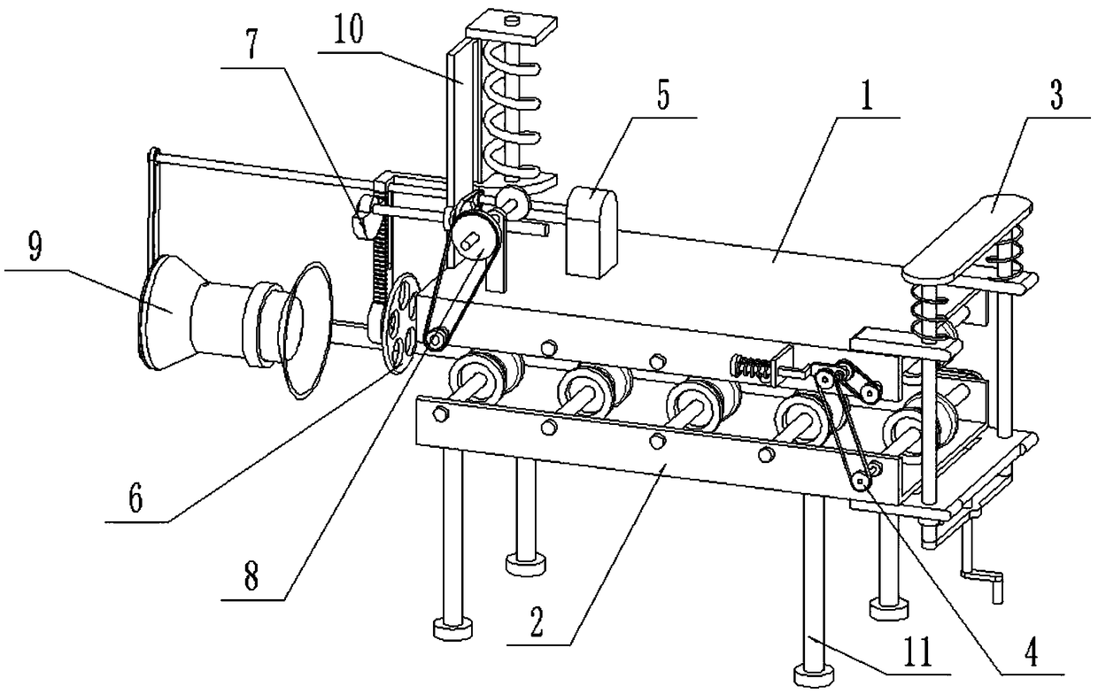
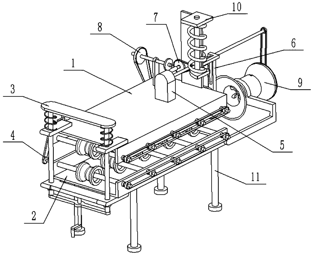
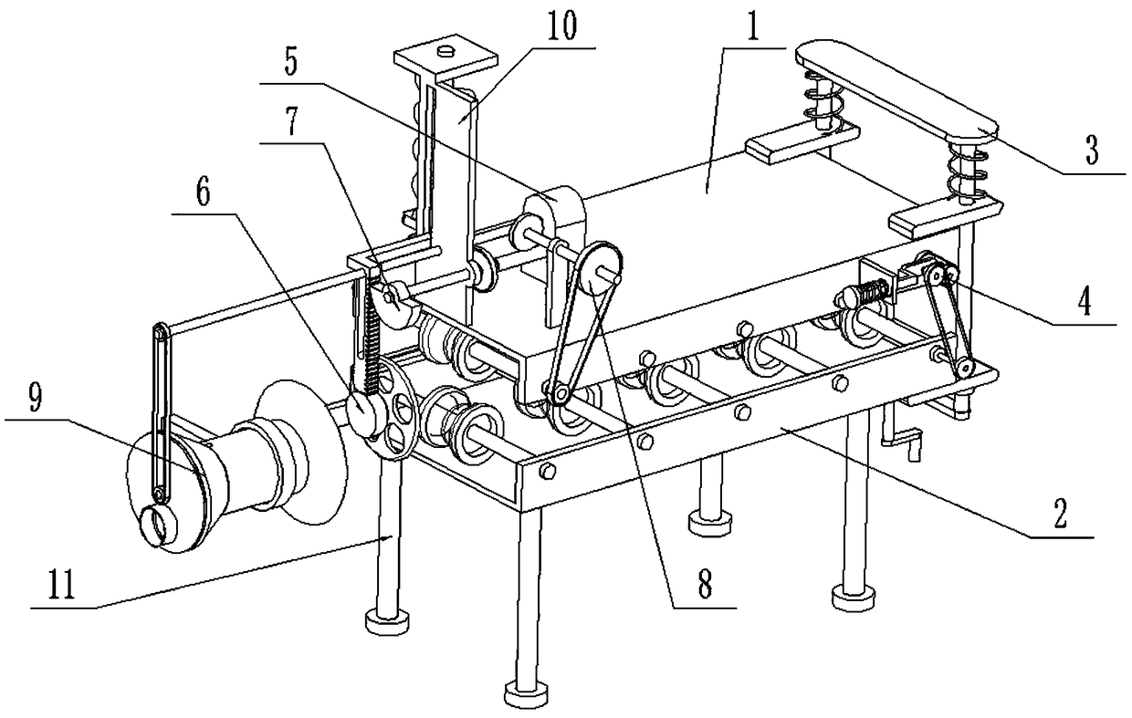
[0035] Such as Figure 1-14 As shown, a cutting device for excess material of plastic products includes an upper feeding table 1, a lower feeding table 2, a vertical adjustment frame 3, a tension linkage wheel 4, a driving mechanism 5, an excess material cutting knife 6, an elevating transmission wheel 7, a speed change Transmission wheel 8, debris collector 9, vertical frame plate 10 and support leg 11, the right end of described upper feeding table 1 is fixedly connected with the upper end of vertical adjustment frame 3, and the lower end of vertical adjustment frame 3 is fixedly connected with lower feeding table 2; Each of the four corners at the bottom of the lower feeding table 2 is fixedly connected with a support leg 11; 4. The transmission is connected to the lower feeding platform 2; when in use, the drive mechanism 5 and the surplus material cutting knife 6 are respectively connected to the power supply through a wire and turned on by a control switch, the drive mec...

specific Embodiment approach 2

[0037] Such as Figure 1-14 As shown, the upper feeding platform 1 includes an upper mounting frame 1-1, an upper feeding pressure roller 1-2, an upper roller shaft 1-3, an upper linkage sprocket 1-4 and an upper linkage chain 1-5; There are multiple roller shafts 1-3, and the multiple upper roller shafts 1-3 are rotatably connected to the upper mounting frame 1-1 through bearings with seats from left to right, and the middle ends of the multiple upper roller shafts 1-3 are fixedly connected. One upper feeding pressure roller 1-2; the rear ends of multiple upper roller shafts 1-3 are each fixedly connected to an upper linkage sprocket 1-4, and the upper linkage chains 1-5 are used for transmission between multiple upper linkage sprockets 1-4 Connection; the drive motor 5-1 is fixedly connected to the top of the upper mounting frame 1-1; the vertical frame plate 10 is fixedly connected to the left side of the top of the upper mounting frame 1-1. When the upper feeding table 1 ...

specific Embodiment approach 3

[0038] Such as Figure 1-14 As shown, the lower feeding platform 2 includes a lower mounting frame 2-1, a lower feeding pressure roller 2-2, a lower roller shaft 2-3, a lower linkage sprocket 2-4 and a lower linkage chain 2-5; There are multiple roller shafts 2-3, and the multiple lower roller shafts 2-3 are rotatably connected to the lower mounting frame 2-1 through bearings with seats from left to right, and the middle ends of the multiple lower roller shafts 2-3 are respectively fixed. Connect a lower feeding pressure roller 2-2; the rear ends of multiple lower roller shafts 2-3 are each fixedly connected to a lower linkage sprocket 2-4, and the lower linkage chain 2-4 is passed between multiple lower linkage sprockets 2-4 5 transmission connection; a plurality of lower feeding pressure rollers 2-2 and a plurality of upper feeding pressure rollers 1-2 are arranged oppositely, and the roller surfaces of the lower feeding pressure rollers 2-2 and the upper feeding pressure ro...


PUM


Abstract

The invention relates to a cutting table, in particular to a cutting device for excess materials of plastic products. The cutting device comprises an upper feeding table, a lower feeding table, a vertical adjusting frame, a tensioning linkage wheel, a driving mechanism, an excess material cutting knife, a lifting transmission wheel, a variable speed transmission wheel, a crushed material collector, a vertical frame plate and supporting legs. The right end of the upper feeding table is fixedly connected to the upper end of the vertical adjusting frame, and the lower end of the vertical adjusting frame is fixedly connected to the lower feeding table; the four corners of the bottom end of the lower feeding table are correspondingly and fixedly connected with the supporting legs; and the tensioning linkage wheel is fixedly connected to the front end of the upper feeding table, the upper feeding table is connected to the tensioning linkage wheel in a transmission mode, and the tensioning linkage wheel is connected to the lower feeding table in a transmission mode. The cutting device is internally provided with the upper feeding table and the lower feeding table, the upper feeding tableand the lower feeding table are matched to convey a plastic pipe to be processed, and the distance between the upper feeding table and the lower feeding table can be adjusted through the vertical adjusting frame to facilitate the use of plastic pipes with different diameters.

Description

technical field [0001] The invention relates to a cutting table, in particular to a device for cutting plastic product residues. Background technique [0002] Plastic products refer to the general designation of daily life, industrial and other supplies processed from plastic as the main raw material. Including plastic as raw material for injection molding, blister and other products of all processes. Plastic is a class of plastic synthetic polymer materials. Together with synthetic plastics and synthetic fibers, it forms the three major synthetic materials indispensable to daily life. Specifically, plastic is a material with natural or synthetic resin as the main component, adding various additives, which can be molded into a certain shape under certain conditions such as temperature and pressure, and is inconvenient to maintain the shape at room temperature. [0003] After the plastic pipe is formed, it can be cut into multiple sections for use. The traditional cutting ...

Claims


Application Information

Patent Timeline
Patent Type & Authority Applications(China)
IPC IPC(8): B26D1/16B26D5/08B26D7/02B26D7/06B26D7/18
CPCB26D1/16B26D5/086B26D7/02B26D7/06B26D7/1863
Inventor 张长芝
Owner 中山市坤源包装材料有限公司
Why Eureka
Try Eureka