Eureka AIR delivers breakthrough ideas for toughest innovation challenges, trusted by R&D personnel around the world.

Method for aligning high-intensity bolt hole sites of connecting plate of steel beam installation via positioning pins

A technology of high-strength bolts and positioning pins, which is applied in the processing of building materials, construction, building construction, etc., which can solve the problems of labor-intensive and installation of mechanical shifts, long time for alignment, and increased investment in construction costs, etc. problems, achieve good economic benefits, easy operation, and reduce construction costs

Inactive Publication Date: 2019-01-15
BEIJING SHOUGANG CONSTR GROUP
View PDF1 Cites 1 Cited by
  • Summary
  • Abstract
  • Description
  • Claims
  • Application Information

AI Technical Summary

Problems solved by technology

[0002] The connecting plate between the steel beam and the steel column of the roof of the industrial factory is fixed with high-strength bolts. During the installation of the steel beam, the bolt holes of the connecting plate between the steel beam and the steel column, and because they belong to the high-strength bolt holes, cannot be cut by gas welding, and are completely dependent on people. With the cooperation of the crane, it takes a long time to find the alignment, which consumes a lot of manpower and installation machinery shifts, which increases the investment in construction costs

Method used


Image

  • Method for aligning high-intensity bolt hole sites of connecting plate of steel beam installation via positioning pins
  • Method for aligning high-intensity bolt hole sites of connecting plate of steel beam installation via positioning pins
  • Method for aligning high-intensity bolt hole sites of connecting plate of steel beam installation via positioning pins

Examples


specific Embodiment approach

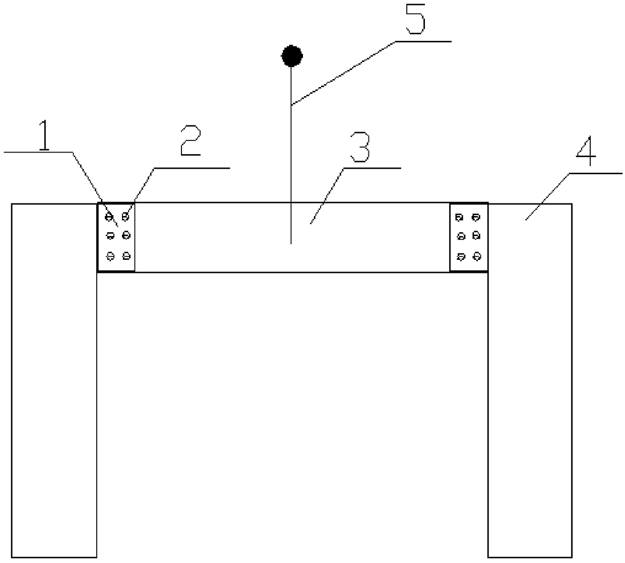
[0018] Figure 1-Figure 7 It is a specific embodiment of the present invention. The specific implementation is as follows:

[0019] In the first step, during the installation of the roof steel beam 3 through the crane sling 5, the high-strength bolt hole 2 that is misaligned between the steel beam 3 and the steel column 4 connecting plate 1 needs to be corrected;

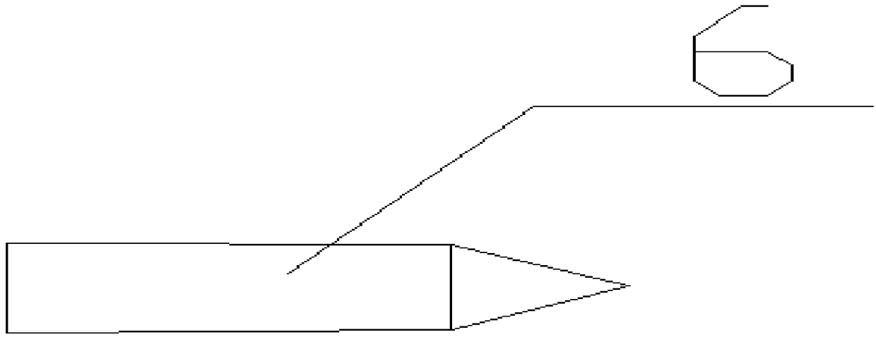
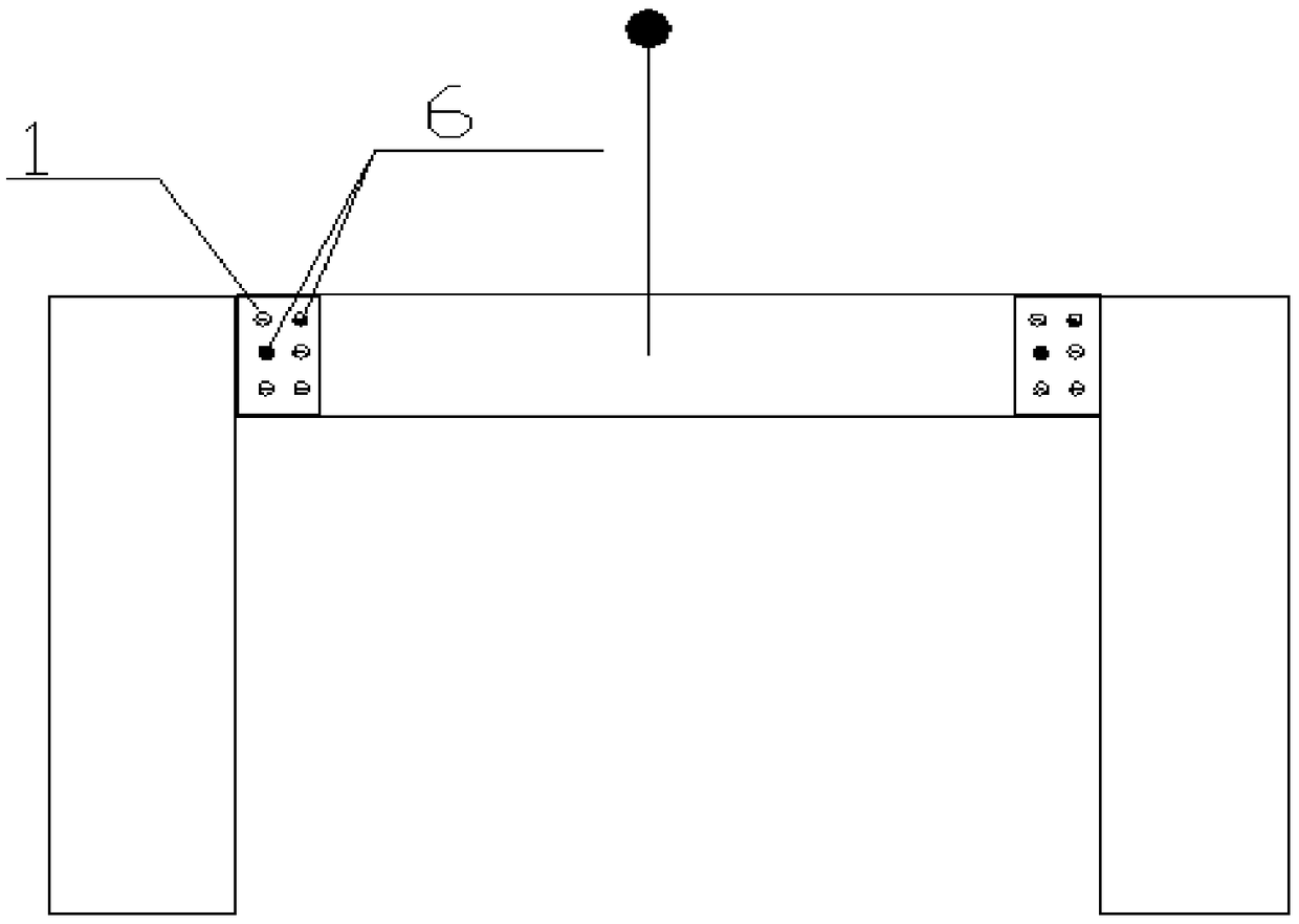
[0020] In the second step, use the processed steel positioning pin 6 to arbitrarily select two high-strength bolt holes 2 with staggered holes in the steel beam 3 and the installation connecting plate 1, and pass through two positioning pins 6;

[0021] The third step is to use external force to hit the positioning pin 6, so that the positioning pin 6 is pushed into the steel beam 3 and the connecting plate 1 to completely align with the high-strength bolt hole 7. The alignment of the two bolt holes determines the bolt holes on all connecting plates. all aligned;

[0022] In the fourth step, high-strength bolts 8...


PUM


Abstract

The invention relates to a method for aligning high-intensity bolt hole sites of a connecting plate of steel beam installation via positioning pins, and belongs to the technical field of roofing steelbeam installation of an industrial workshop. The method comprises the steps that in the process that a roofing steel beam (3) is installed via a suspension cable (5) of a crane, and offset the high-intensity bolt hole sites (2) appear in the steel beam (3) and the steel column (4) connecting plate (1) respectively, and need to be aligned and located; the processed steel positioning pins (6) are used, two offset high-intensity bolt hole sites (2) are selected from the steel beam (3) and the installation connecting plate (1), and the two positioning pins (6) penetrate the hole sites respectively; the positioning pins (6) are knocked by an outside force, so that the positioning pins (6) are pushed into the steel beam (3) and the connecting plate (1) and completely aligned with the high-intensity bolt hole site (7), and all bolt holes in the connecting plate are aligned if only the two bolt holes are aligned; and high-intensity bolts (8) are mounted, and the positioning pins (6) are dismounted by knocking at the same time and are recovered for cyclic use. The method has the advantages that operation is easy, it is ensured that the roofing steel beam can be installed rapidly, the installation efficiency is improved greatly, a hoisting facility is used fully, and the construction cost is reduced.

Description

technical field [0001] The invention belongs to the technical field of installing roof steel beams of industrial factories, and in particular provides a method for aligning high-strength bolt hole positions of steel beam installation connecting plates by using positioning pins. Background technique [0002] The connecting plate between the steel beam and the steel column of the roof of the industrial factory is fixed with high-strength bolts. During the installation of the steel beam, the bolt holes of the connecting plate between the steel beam and the steel column, and because they belong to the high-strength bolt holes, cannot be cut by gas welding, and are completely dependent on people. With the cooperation of the crane, it takes a long time to find the alignment, which consumes a lot of manpower and installation machinery shifts, which increases the investment in construction costs. Contents of the invention [0003] The purpose of the present invention is to provide...

Claims


Application Information

Patent Timeline
Patent Type & Authority Applications(China)
IPC IPC(8): E04G21/14
CPCE04G21/14
Inventor 纪磊
Owner BEIJING SHOUGANG CONSTR GROUP
Why Eureka
Eureka Blog
Learn More