
Involute surface multi-cavity oscillating pump

A technology of swing pump and involute surface, which is applied in the field of multi-cavity swing pump with involute surface, can solve the problem of restricting the application fields of single-acting vane pump and double-acting vane pump, aggravating the friction and wear of blade and blade chute, affecting the blade, The service life of the chute and other issues have been achieved to achieve the effects of low vibration and noise, reduced speed requirements, and reduced friction

Active Publication Date: 2019-11-12
CHANGZHOU UNIV
View PDF5 Cites 0 Cited by
  • Summary
  • Abstract
  • Description
  • Claims
  • Application Information

AI Technical Summary

Problems solved by technology

When single-acting vane pumps and double-acting vane pumps are working, the force exerted by the inner wall of the pump on the vanes has a certain angle to the center line of the vanes, so that the vanes are subjected to a bending moment exerted by the inner wall of the pump, which intensifies the gap between the vanes and the vane chute. The friction and wear between them affect the service life of blades and chute
In addition, the vanes of single-acting vane pumps and double-acting vane pumps rely on their centrifugal force to achieve contact and sealing between the vane and the inner wall of the pump, so the pump rotor speed is required to be high enough, which limits the single-acting vane pump and double-acting vane pump. field of application

Method used


Image

  • Involute surface multi-cavity oscillating pump
  • Involute surface multi-cavity oscillating pump

Examples


Embodiment Construction

[0019] The present invention will be described in further detail below in conjunction with the accompanying drawings and specific embodiments.

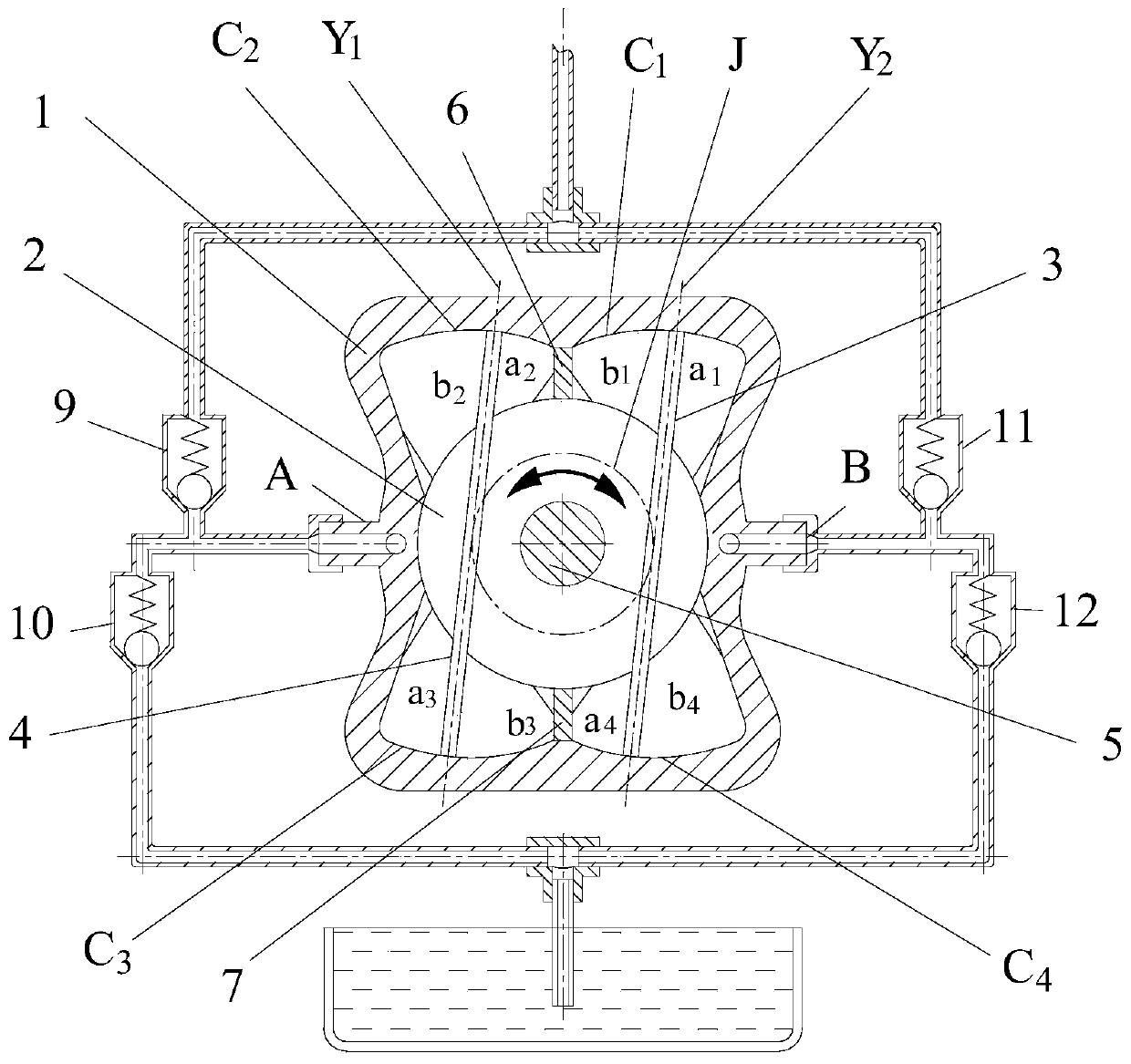
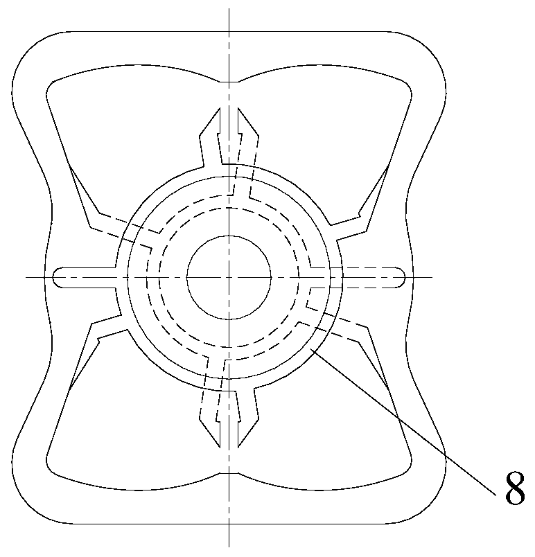
[0020] Figure 1 to Figure 2 It is an embodiment disclosed by the present invention. The involute surface multi-chamber swing pump of the present invention consists of a pump body 1, a rotor 2, a right vane 3, a left vane 4, a transmission shaft 5, an upper partition 6, a lower partition 7, a flow plate 8, oil ports A and B, Check valve 9 to 12 etc. form. There are four involute surfaces on the inner wall of the pump body 1: C 1 、C 2 、C 3 、C 4 , their corresponding base cylinders are all J, and the four involute surfaces C 1 、C 2 、C 3 、C 4 The positions are symmetrical and the dimensions are the same. The rotor 2 is provided with two chutes parallel to each other and symmetrical with respect to the center of the rotor. The distance between the centerlines of the two chutes is equal to the diameter of the base cylinder J. The...


PUM


Abstract

The invention provides an involute surface multi-cavity oscillating pump, which comprises a pump body (1), a rotor (2), blades (3,4), a rotation shaft (5), partition plates (6,7), a valve plate (8), non-return valves (9, 10, 11, 12), and oil ports (A,B). Four involute surfaces (C1, C2, C3, C4), which are symmetric and are generated from a basic column (J), are arranged on the inner wall of the pump body (1). Two ends of the blades (3,4) are always pressed against to the corresponding involute surfaces. Two chutes, which are parallel to each other and are symmetrical relative to the center of the rotor (2), are arranged in the rotor (2), and the distance between two chutes is equal to the diameter of the basic column (J). The blades (3,4) are installed in two chutes, and the length of the blades (3,4) is equal to the normal distance between the involute surface (C1) and the involute surface (C4). Four symmetrical oil discharge cavities can simultaneously output pressure oil; the oil pumping efficiency is high, moreover, the quantity is controllable, the radial force on the transmission shaft is balanced, the wear between the blades and the chutes is small, and the service life of the pump is long.

Description

technical field [0001] The invention relates to the technical field of vane pumps, in particular to an involute surface multi-cavity swing pump. Background technique [0002] Vane pump is a kind of hydraulic pump widely used in hydraulic transmission system. It can be divided into two categories: single-acting vane pump and double-acting vane pump in structure. They are composed of pump body, vane, rotor, flow plate, transmission shaft, pump cover etc. The single-acting vane pump is variable, but the radial hydraulic pressure on the transmission shaft is unbalanced, and its bearing load is relatively large. The radial hydraulic pressure on the drive shaft of the double-acting vane pump is balanced, but not variable. When single-acting vane pumps and double-acting vane pumps are working, the force exerted by the inner wall of the pump on the vanes has a certain angle to the center line of the vanes, so that the vanes are subjected to a bending moment exerted by the inner wa...

Claims


Application Information

Patent Timeline
Patent Type & Authority Patents(China)
IPC IPC(8): F04C9/00F04C15/00F04C15/06
CPCF04C9/002F04C15/00F04C15/0042F04C15/0061F04C15/06F04C2240/10F04C2240/20
Inventor 邹旻祝海林乔永强任爽李亮亮
Owner CHANGZHOU UNIV
Learn More