
Multi-stage pump

A multi-stage pump and pump body technology, applied in the field of multi-stage pumps, can solve the problems of poor anti-cavitation performance of multi-stage pumps, and achieve the effects of overcoming occlusion, improving safety and reliability, and overcoming damage

Pending Publication Date: 2019-01-15
无锡艾比德泵业有限公司
View PDF0 Cites 2 Cited by
  • Summary
  • Abstract
  • Description
  • Claims
  • Application Information

AI Technical Summary

Problems solved by technology

Existing multi-stage pumps cannot guarantee high-efficiency operation under various complex working conditions, and the anti-cavitation performance of multi-stage pumps is poor

Method used


Image

  • Multi-stage pump
  • Multi-stage pump
  • Multi-stage pump

Examples


Embodiment Construction

[0031] The specific implementation of this embodiment will be described below in conjunction with the accompanying drawings.

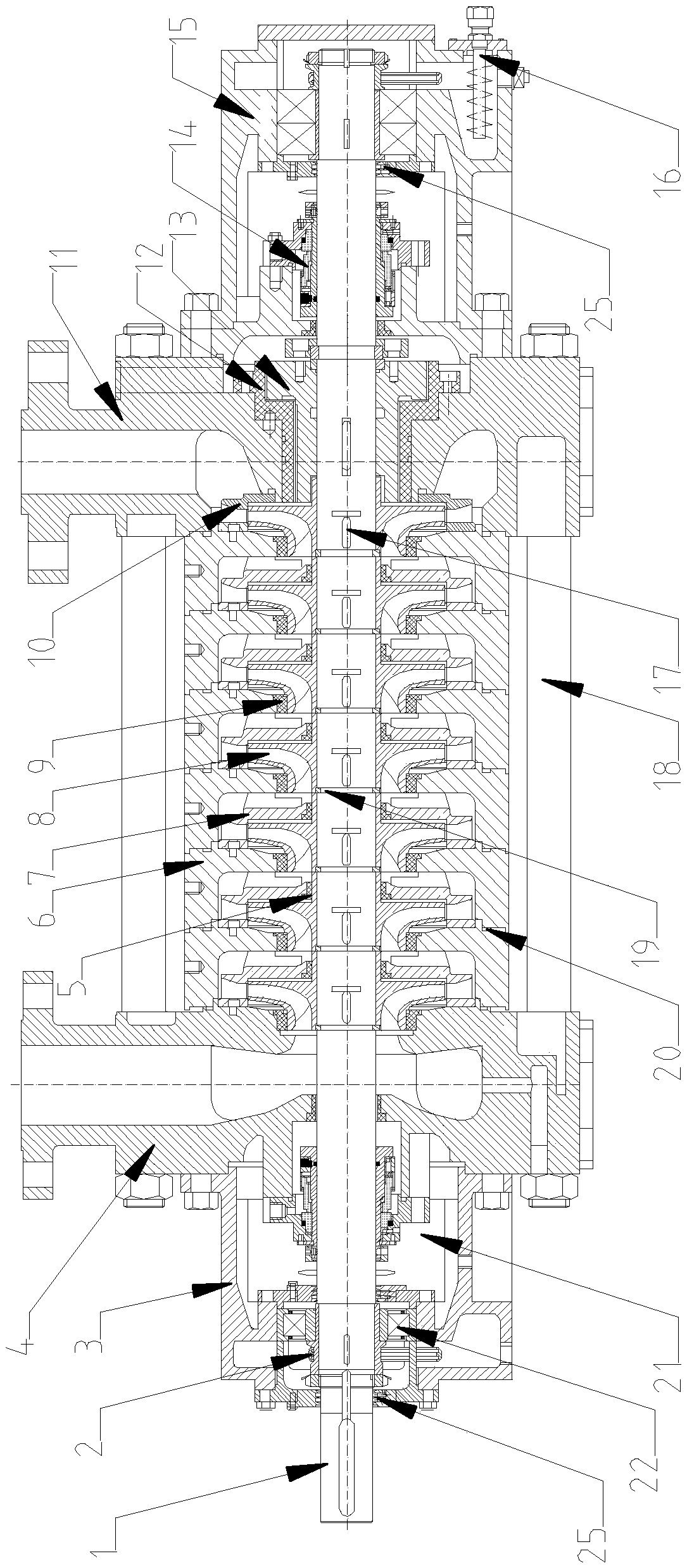
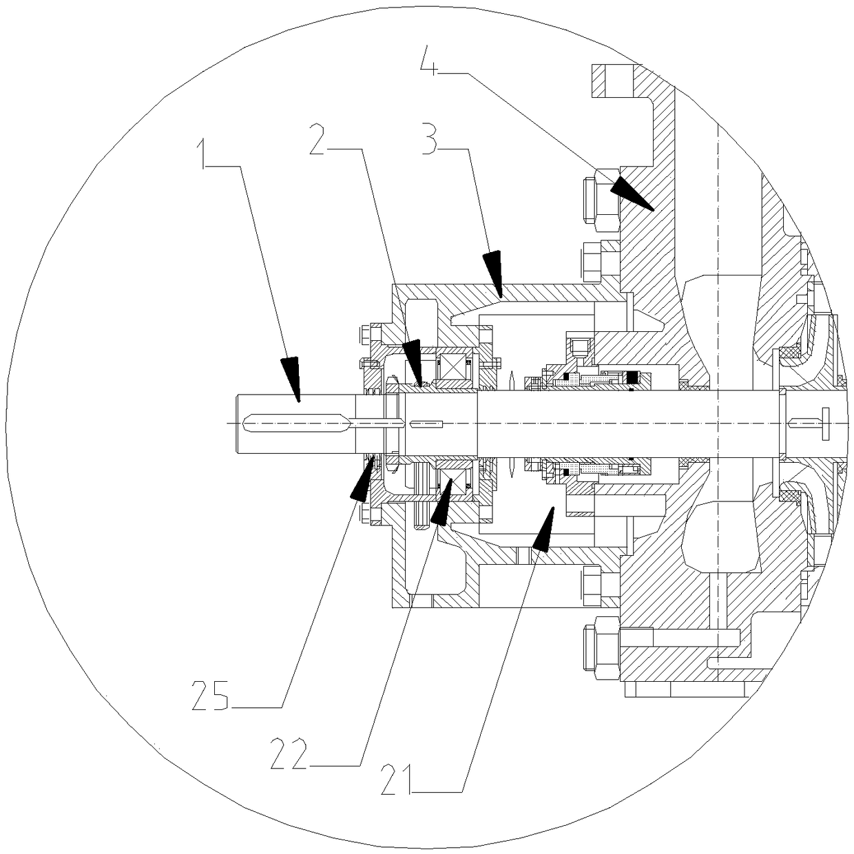
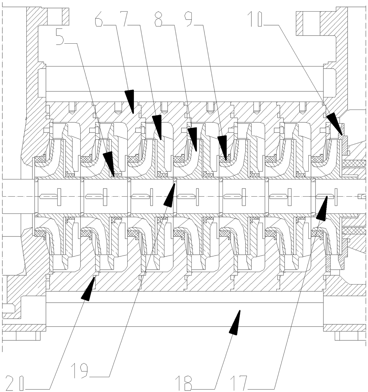
[0032] figure 1 It is a schematic diagram of the present invention. Such as figure 1 As shown, the multistage pump includes a pump shaft 1 , a driving end bearing assembly 3 , a water inlet section pump body 4 , a multistage middle section pump body 6 , a water outlet section pump body 11 and a non-driving end bearing assembly 15 . The pump body 4 of the water inlet section, the pump body 6 of the multi-stage middle section and the pump body 11 of the water outlet section are sleeved on the pump shaft 1 in sequence, and the two sides of the pump body 4 of the water inlet section and the two sides of the pump body 11 of the water outlet section pass through the pull rods 18 respectively. Connected together, the nut is sleeved on the pull rod 18, and the nut is tightened to clamp the water inlet section pump body 4, the multi-stage middle section pump ...


PUM


Abstract

The invention relates to a multi-stage pump. The multi-stage pump comprises a pump shaft, a driving end bearing assembly, a water inlet segment pump body, a multi-stage middle-segment pump body, a water outlet segment pump body, a non-driving-end bearing assembly, guide vanes, impellers, a balance disk and a cooling device, wherein the water inlet segment pump body, the multi-stage middle-segmentpump body and the water outlet segment pump body are sleeved on the pump shaft in sequence; both sides of the water inlet segment pump body and the water outlet segment pump body are connected together through pull rods; the driving end bearing assembly is arranged at one end of the pump shaft; the non-driving end bearing assembly is arranged at the other end of the pump shaft; annular cavities are formed between the water inlet segment pump body and a first-stage middle-segment pump body, between two adjacent middle-segment pump bodies, at a tail-stage middle-segment pump body and the water outlet segment pump body; both the guide vanes and the impellers are arranged in the cavities; the impellers are fixed on the pump shaft through buttons; the guide vanes are sleeved on the outer sidesof the impellers; the balance disk is fixed to the right side of a tail-stage impeller; the cooling device is arranged on the lower side of the non-driving end bearing assembly. By adopting the multi-stage pump, the independent stress on the impellers is reduced and the accumulated error due to assembly of multi-stage impellers is reduced.

Description

technical field [0001] The invention relates to the field of water pumps, in particular to a multistage pump. Background technique [0002] According to the structure, multi-stage pumps can be divided into single-suction chemical centrifugal pumps, multi-stage chemical centrifugal pumps, segmental chemical centrifugal pumps, horizontal chemical centrifugal pumps, etc. Multistage pumps are mainly used in seawater desalination, environmental protection engineering, thermal power industrial devices and other fields. Multi-stage pumps mainly transport all kinds of clean or suspended medium, corrosive or non-corrosive medium without particles. [0003] The basic structure of multistage pump is composed of water inlet section, water outlet section, middle section, tail cover, impeller, pump body, pump shaft, bearing, sealing ring, stuffing box and other components. Multistage pumps are mainly suitable for working conditions with high head and large flow. The output water pressu...

Claims


Application Information

Patent Timeline
Patent Type & Authority Applications(China)
IPC IPC(8): F04D1/06F04D29/20F04D29/58F04D29/42F04D29/08F04D29/046F04D29/02
CPCF04D1/06F04D29/026F04D29/046F04D29/086F04D29/20F04D29/426F04D29/588
Inventor 吴明亮杜志高
Owner 无锡艾比德泵业有限公司
Learn More