
Rotary dry steam humidification device

A humidification device and dry steam technology, which is applied in air humidification systems, heating methods, lighting and heating equipment, etc., can solve the problems that the mist has not been filtered and sterilized, which affects people's normal use and hidden dangers in safe use, and is convenient for widespread promotion. and use, improve humidification efficiency, convenient and safe use effect

Inactive Publication Date: 2019-01-15
浙江杭强制冷设备股份有限公司
View PDF7 Cites 0 Cited by
  • Summary
  • Abstract
  • Description
  • Claims
  • Application Information

AI Technical Summary

Problems solved by technology

Traditional humidifiers have a fixed outlet structure, and the spray outlet of the humidifier is usually in a fixed direction. During long-term use, it is found that the humidification process takes a long time, because its air flow will directly lead to its humidification. The uniformity of the space; the currently used humidifiers usually have water droplets at the humidification spray port, which seriously affects people's normal use; and the mist sprayed by the humidifier has not been filtered and sterilized, and there will be great safety problems. Hidden danger

Method used


Image

  • Rotary dry steam humidification device

Examples


Embodiment Construction

[0016] In order to make the technical problems, technical solutions and beneficial effects solved by the present invention clearer, the present invention will be further described in detail below in conjunction with the accompanying drawings and embodiments. It should be understood that the specific embodiments described here are only used to explain the present invention, not to limit the present invention.

[0017] In the description of the present invention, it should be understood that the terms "one side", "the other side", "both sides", "middle", "inside", "upper end", "lower end", "upper" , "lower", "top" and other indicated orientations or positional relationships are based on the orientations or positional relationships shown in the drawings, and are only for the convenience of describing the present invention and simplifying the description, rather than indicating or implying that the referred device or element must Having a particular orientation, being constructed ...


PUM


Abstract

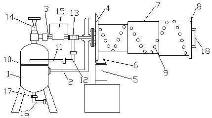
The invention relates to a rotary dry steam humidification device. The rotary dry steam humidification device is provided with a steam-water separation tank, a steam inlet pipe is connected to one side of the steam-water separation tank through a pipeline, a steam outlet pipe is arranged at the upper end of the steam-water separation tank, and the steam outlet pipe communicates with an injection assembly; the injection assembly comprises a first bevel gear, a driving motor, a second bevel gear, an injection cavity and a sealing sleeve; the injection cavity is connected to the end portion of the steam outlet pipe in a sealing mode, the injection cavity is of a telescopic ladder columnar structure, and an injection opening is spirally formed in the injection cavity in the length direction; the first bevel gear is fixedly arranged at one end of the injection cavity, the second bevel gear is connected with the lower end of the first bevel gear in a meshing mode, and the driving motor is fixed to the lower end of the second bevel gear; and the sealing sleeve is fixedly arranged at the other end of the injection cavity. The rotary dry steam humidification device has a simple structure, can promote rapid and uniform dispersion of humidified mist, shorten the humidification time, and improve the humidification efficiency, the injected mist is clean, environmental friendly and healthy after treatment, safe use of people is convenient, and wide popularization and use are facilitated.

Description

technical field [0001] The invention relates to the technical field of humidifiers, in particular to a rotary dry steam humidifier. Background technique [0002] With the continuous development of society, humidifiers have been widely used in all walks of life. Traditional humidifiers have a fixed outlet structure, and the spray outlet of the humidifier is usually in a fixed direction. During long-term use, it is found that the humidification process takes a long time, because its air flow will directly lead to its humidification. The uniformity of the space; the currently used humidifiers usually have water droplets at the humidification spray port, which seriously affects people's normal use; and the mist sprayed by the humidifier has not been filtered and sterilized, and there will be great safety problems. Hidden danger. Contents of the invention [0003] The technical problem to be solved by the present invention is: in order to solve the problems existing in the ab...

Claims


Application Information

Patent Timeline
Patent Type & Authority Applications(China)
IPC IPC(8): F24F6/12F24F13/28F24F13/00F24F11/89
CPCF24F6/12F24F11/89F24F13/00F24F13/28
Inventor 王连兴
Owner 浙江杭强制冷设备股份有限公司
Learn More