Remote water quality detecting device

A water quality detection device and remote technology, applied in the direction of measuring devices, sampling devices, testing water, etc., can solve the problems that automatic sampling and detection cannot be realized, and achieve the effect of improving convenience and reducing work intensity

Inactive Publication Date: 2019-01-15
钟万平
0 Cites 2 Cited by

AI-Extracted Technical Summary

Problems solved by technology

[0004] In view of the deficiencies in the prior art, the purpose of the present invention is to provide a remote water quality detection device to solve the problem that the existing water quality detection...

Method used

Metering pump 1 of the present invention, accommodation box 2, water quality sampling pipe 3, transmission wire 4, photoelectric detector 5, remote data acquisition controller 6, power controller 7, water quality detector 8, support 9, water Lower radiation rod 11, photoelectric signal detection module 51, display screen 61, control buttons 62, signal receiver 63, wireless data transmission module 64, data storage module 65, main control module 66, management center 67, control panel 68, all components are It is a general standard part or a component known to those skilled in the art. Its structure and principle are known to those skilled in the art through technical manuals or through conventional experimental methods. The problem solved by the present invention is that the prior art cannot realize automatic samplin...

Abstract

The invention discloses a remote water quality detecting device, comprising a metering pump, a receiving box, a water quality sampling tube, a transmission line, a photoelectric detector, a remote data acquisition controller, a power controller, a water quality detector and a bracket. The bottom of the water quality detector is welded to the bracket. The remote data acquisition controller is disposed inside the water quality detector, and the photoelectric detector is disposed on the outer surface of the water quality detector. The photoelectric detector is embedded in the water quality detector, and is provided with a photoelectric signal detection module. The top of the water quality detector is perpendicular to the power controller, and the water quality detector is electrically connected to the metering pump through a transmission wire. The receiving box is disposed on the metering pump, and the receiving box and the metering pump are perpendicular to each other. According to the remote water quality detecting device, the automatic sampling detection can be realized through the cooperation between the photoelectric detector and the remote data acquisition controller, and the data can be transmitted remotely, without the need for inspectors to perform field detections, thereby improving the convenience and reducing the work intensity.

Application Domain

Withdrawing sample devicesMaterial analysis by optical means +2

Technology Topic

Transmission lineElectricity +8

Image

  • Remote water quality detecting device
  • Remote water quality detecting device

Examples

  • Experimental program(1)

Example Embodiment

[0016] In order to make the technical means, creative features, objectives and effects of the present invention easy to understand, the present invention will be further explained below in conjunction with specific embodiments.
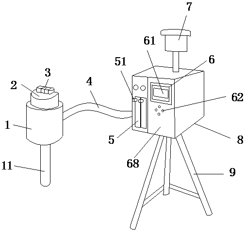
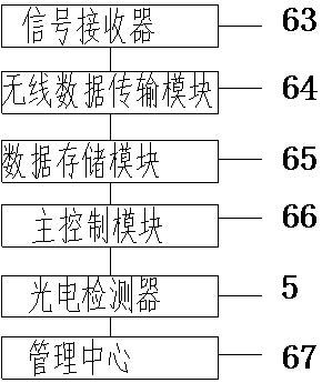
[0017] See Figure 1 to Figure 2 , The present invention provides a technical solution for a remote water quality detection device: its structure includes a metering pump 1, a containing box 2, a water quality sampling tube 3, a transmission wire 4, a photoelectric detector 5, a remote data acquisition controller 6, and a power controller 7. , Water quality detector 8, bracket 9, the bottom of the water quality detector 8 is welded to the bracket 9, the remote data acquisition controller 6 is installed inside the water quality detector 8, the photoelectric detector 5 is installed on the water quality detector 8 On the outer surface, the photoelectric detector 5 is embedded in the water quality detector 8. The photoelectric detector 5 is provided with a photoelectric signal detection module 51. The top of the water quality detector 8 is perpendicular to the power controller 7, and the water quality The detector 8 is electrically connected to the metering pump 1 through a transmission wire 4, and a housing box 2 is provided above the metering pump 1, the housing box 2 and the metering pump 1 are perpendicular to each other, and the water quality sampling pipe 3 is provided in the housing. On the box 2, the water quality sampling pipe 3 and the metering pump 1 are connected, and the remote data acquisition controller 6 is composed of a display screen 61, a control button 62, a signal receiver 63, a wireless data transmission module 64, a data storage module 65, The main control module 66, the management center 67 and the control panel 68 are composed of the display 61, the control buttons 62 are installed on the outer surface of the control panel 68, the display 61, the control buttons 62, the signal receiver 63, the wireless data The transmission module 64, the data storage module 65, the management center 67 are connected to the main control module 66 through a single connection, and the main control module 66 is electrically connected to the photodetector 5, and the metering pump 1 is provided with an underwater radiation rod 11, The underwater radiant rod 11 is perpendicular to the metering pump 1, the support 9 is composed of four or more square steel pipes connected in sequence, the underwater radiant rod 11 is a columnar structure, the support 9 is a triangular structure, and the power The controller 7 provides power for the device, and the display 61 is a liquid crystal display.
[0018] The photodetector 5 mentioned in this patent mainly uses electronic technology to detect optical signals, and further transmits, stores, controls, calculates and displays. In principle, photoelectric detection technology can detect all non-electrical quantities that can affect the amount of light and light characteristics. It can transform the non-electricity information to be detected into easily acceptable optical information through the optical system.
[0019] When using the remote water quality detection device of the present invention, first place the metering pump 1 and the water quality detector 8 on the place where water quality detection is required, and they are installed and fixed by the bracket 9, and the underwater radiation rod 11 prevents the back of the sun. The metering pump 1 effectively extracts the water source to be detected and saves it in the water quality sampling tube 3. The photoelectric detector 5 continuously monitors the optical characteristics of the water body. Combined with other water quality parameters, it can provide early warning of the occurrence of water bloom, and The data is saved and sent to the main control module 66, and the main control module 66 sends the data to the management center 67 according to the wireless data transmission module 64. For example, the water quality detection device can be used for detection in a reservoir.
[0020] The metering pump 1, containing box 2, water quality sampling pipe 3, transmission wire 4, photoelectric detector 5, remote data acquisition controller 6, power controller 7, water quality detector 8, bracket 9, underwater radiation rod of the present invention 11. Photoelectric signal detection module 51, display 61, control buttons 62, signal receiver 63, wireless data transmission module 64, data storage module 65, main control module 66, management center 67, control panel 68, all components are common standards The structure and principle of components or components known to those skilled in the art are all known to those skilled in the technical manual or through conventional experimental methods. The problem solved by the present invention is that the prior art cannot achieve automatic sampling and detection, and Data is transmitted remotely, and inspection personnel need to perform on-site inspection to improve work intensity. Through the combination of the above-mentioned components, the present invention can realize automatic sampling and inspection through the cooperation between the photoelectric detector and the remote data acquisition controller, and the data Remote transmission, no need for inspection personnel to conduct on-site inspection, which improves convenience and reduces work intensity, as described below:
[0021] The remote data acquisition controller 6 is composed of a display screen 61, a control button 62, a signal receiver 63, a wireless data transmission module 64, a data storage module 65, a main control module 66, a management center 67 and a control panel 68. The display The screen 61, the control buttons 62 are installed on the outer surface of the control panel 68, the display 61, the control buttons 62, the signal receiver 63, the wireless data transmission module 64, the data storage module 65, the management center 67 and the main control module 66 Through a single connection, the main control module 66 and the photodetector 5 are electrically connected.
[0022] The photoelectric detector 5 of this embodiment is embedded in the water quality detector 8 to realize automatic sampling and detection, and remotely transmit the data, eliminating the need for detection personnel to perform on-site detection, improving convenience and reducing work intensity.
[0023] The above shows and describes the basic principles and main features of the present invention and the advantages of the present invention. For those skilled in the art, it is obvious that the present invention is not limited to the details of the above exemplary embodiments, and does not deviate from the spirit or basics of the present invention. In the case of features, the present invention can be implemented in other specific forms. Therefore, from any point of view, the embodiments should be regarded as exemplary and non-limiting. The scope of the present invention is defined by the appended claims rather than the foregoing description, and therefore it is intended to fall within the claims. All changes within the meaning and scope of equivalent elements of are included in the present invention. Any reference signs in the claims should not be regarded as limiting the claims involved.
[0024] In addition, it should be understood that although this specification is described in accordance with the implementation manners, not each implementation manner only includes an independent technical solution. This narration in the specification is only for clarity, and those skilled in the art should consider the specification as a whole The technical solutions in the embodiments can also be appropriately combined to form other implementations that can be understood by those skilled in the art.

PUM

no PUM

Description & Claims & Application Information

We can also present the details of the Description, Claims and Application information to help users get a comprehensive understanding of the technical details of the patent, such as background art, summary of invention, brief description of drawings, description of embodiments, and other original content. On the other hand, users can also determine the specific scope of protection of the technology through the list of claims; as well as understand the changes in the life cycle of the technology with the presentation of the patent timeline. Login to view more.

Similar technology patents

Payment method, payment device and wearable device

Owner:YULONG COMPUTER TELECOMM SCI (SHENZHEN) CO LTD

Network scanning system

InactiveUS20050057780A1improve conveniencelow cost
Owner:CANON DENSHI KK

Classification and recommendation of technical efficacy words

  • Improve convenience
  • Reduce work intensity

Powerless voltage automatic control system for area power grid

InactiveCN101106274AReduce network loss and operating costsReduce work intensity
Owner:SHANGHAI JIAO TONG UNIV

Quick automatic artillery aiming device

InactiveCN101881580AReduce work intensityImprove emission efficiency
Owner:ZHEJIANG UNIV OF TECH

Concrete laminating curing machine

Owner:盐城欣昌新型建材有限公司
Why Eureka
Try Eureka