Optical-fiber scanning imaging system and optical-fiber scanning imaging equipment

A fiber optic scanning and imaging system technology, applied in the electronic field, can solve problems affecting image display effects

Pending Publication Date: 2019-01-15
CHENGDU IDEALSEE TECH
View PDF6 Cites 2 Cited by
  • Summary
  • Abstract
  • Description
  • Claims
  • Application Information

AI Technical Summary

Problems solved by technology

[0006] Embodiments of the present invention provide a fiber scanning imaging system and fiber scanning imaging equipment to solve the technical probl...

Method used


Image

  • Optical-fiber scanning imaging system and optical-fiber scanning imaging equipment
  • Optical-fiber scanning imaging system and optical-fiber scanning imaging equipment
  • Optical-fiber scanning imaging system and optical-fiber scanning imaging equipment

Examples


Embodiment Construction

[0027] The following will clearly and completely describe the technical solutions in the embodiments of the present invention with reference to the accompanying drawings in the embodiments of the present invention. Obviously, the described embodiments are only some, not all, embodiments of the present invention. Based on the embodiments of the present invention, all other embodiments obtained by persons of ordinary skill in the art without creative efforts fall within the protection scope of the present invention.

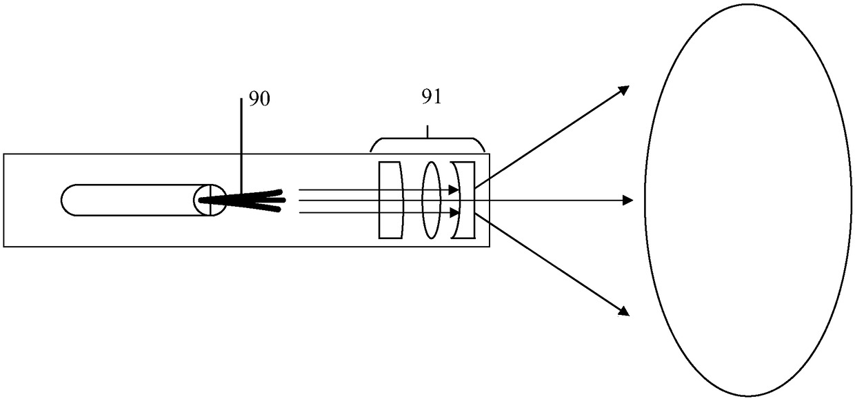
[0028] Embodiments of the present invention provide an optical fiber scanning imaging system and an optical fiber scanning imaging device to solve the technical problem in the prior art that the display effect of an image formed by scanning is affected by the divergence of the light beam emitted from the optical fiber.

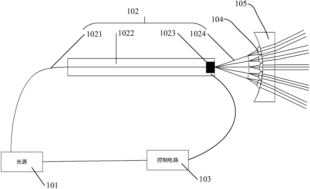
[0029] The first aspect of the embodiment of the present invention provides an optical fiber scanning imaging system, please refer to figure 2 , ...


PUM


Abstract

The invention discloses an optical-fiber scanning imaging system and optical-fiber scanning imaging equipment. The optical-fiber scanning imaging system includes an optical source, scanning optical-fiber, a control circuit, a collimating microlens array and an angle expanding lens group. Optical beams exiting the optical source are coupled into the scanning optical-fiber, then exits from the scanning optical-fiber, then is collimated by the collimating microlens array, then passes through the angle expanding lens group, and then exits. A technical scheme of collimating, through the collimatingmicrolens array, the optical beams exiting from the scanning optical-fiber is employed, thus collimation of the optical beams exiting from all collimating microlenses in the collimating microlens array is ensured, resolution of images formed by scanning of the optical-fiber scanning imaging system is also ensured, thus a display effect of the images formed by scanning is ensured, and cases wherethe optical beams exiting from the scanning optical-fiber becomes thicker with distance increasing, and thus the display effect of the images formed by scanning is impacted are avoided.

Description

technical field [0001] The invention relates to the field of electronic technology, in particular to an optical fiber scanning imaging system and optical fiber scanning imaging equipment. Background technique [0002] Optical fiber scanning technology is one of the future development trends of scanning display technology due to its strong color performance, high brightness, long life, small size, light weight and low power consumption. [0003] When scanning through the optical fiber, according to the different numerical apertures of the optical fiber, there are different degrees of divergence in the light emitted from the optical fiber, but the light will become thicker with the increase of the outgoing distance. Larger light spots will be formed on the projection surface such as the wall, which will affect the resolution and screen size of the image formed by scanning, thereby affecting the display effect of the image formed by scanning. [0004] Please refer to figure 1...

Claims


Application Information

Patent Timeline
IPC IPC(8): G02B26/10
CPCG02B26/103
Inventor 周旭东喻秀英姚长呈
Owner CHENGDU IDEALSEE TECH
Why Eureka
Try Eureka