Connector

A connector and active connection technology, applied in the direction of connection, fixed connection, circuit, etc., can solve the problems of complex structure and process, product failure, high mold cost, and achieve simple structure and process, improve reliability, and low mold cost. Effect

Pending Publication Date: 2019-01-15
NIO CO LTD
View PDF5 Cites 0 Cited by
  • Summary
  • Abstract
  • Description
  • Claims
  • Application Information

AI Technical Summary

Problems solved by technology

[0009] The purpose of the embodiment of the present invention is to provide a connector, which is flexibly connected to the second insulator through the first insulator, and a buffer part is provided on the conductive terminal, so as to solve the problem in the prior art when a connector connects two layers of circuit boards. Solder joints are prone to cracking under high temperature shock and strong vibration, leading to technical problems of product failure; since the conductive terminal does not have the problem of mating the male end and the female end, it solves the problem of using a male-female end board-to-board connector to connect two terminals in the prior art. When layering circuit boards, the female end needs to meet the requirements of flexibility and tolerance matching in all directions, and a special structural design is required, which makes the structure and process of the female end complicated, and the cost of the mold is high, resulting in the technical problem of high cost of the board-to-board connector. ; By changing the cross-sectional area of ​​the conductive terminal, the requirement of high current can be met, which solves the problem that the connector in the prior art adopts the method of arranging wires. technical problem

Method used


Image

  • Connector
  • Connector
  • Connector

Examples


Embodiment Construction

[0034] In order to make the object, technical solution and advantages of the present invention clearer, the present invention will be further described in detail below in combination with specific embodiments and with reference to the accompanying drawings. It should be understood that these descriptions are exemplary only, and are not intended to limit the scope of the present invention. Also, in the following description, descriptions of well-known structures and techniques are omitted to avoid unnecessarily obscuring the concept of the present invention.

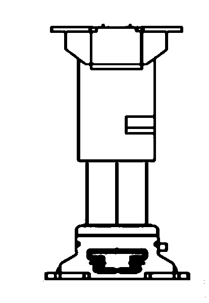
[0035] Figure 4 It is a structural schematic diagram of the connector provided by the embodiment of the present invention.

[0036] Figure 5 is a schematic structural diagram of the first insulator provided by the embodiment of the present invention.

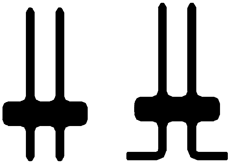
[0037] Figure 6 is a schematic structural diagram of a conductive terminal provided by an embodiment of the present invention.

[0038] Figure 7 It is a structura...


PUM


Abstract

A connector, belonging to the technical field of circuit board connection, comprises: a first insulator (1) provided with a plurality of through holes (11); A second insulator (2) disposed opposite toand movably connected to the first insulator (1); A plurality of conductive terminals (3), one end of each conductive terminal (3) passing through the through hole (11) and the other end passing through the second insulator (2) and fixedly connected to the second insulator (2); Each conductive terminal (3) is partially arched between the first insulator (1) and the second insulator (2) to form abuffer (31). As that connector is movably connected with the second insulator and the conductive terminal itself is flexible to absorb the vibration and the stress of the cold and heat shock, the stress of the solder joint is reduce, and the reliability of the product is improved; At that same time, the structure and the process of the conductive terminal are simple, so that the cost of the connector is reduced; When used with large currents, the area of the board does not increase.

Description

technical field [0001] The invention relates to the technical field of circuit board connection, in particular to a connector. Background technique [0002] In order to improve space utilization and increase power density. Now the controller is developing in the direction of miniaturization and integration. Due to the improvement of functional requirements, the limitation of the integration of electronic devices and the limitation of the volume of the controller, usually one circuit board cannot arrange all the devices. In most cases, all devices are placed on a circuit board with a layer of circuit boards. In order to realize the signal and circuit connection between the two boards, a connector is needed to connect the two boards. [0003] Especially in the automotive industry, controllers are subject to strong vibration and temperature shocks. This causes the relative positions of the two layers of boards to move away and get closer. Under strong impact, the single-la...

Claims


Application Information

Patent Timeline
Patent Type & Authority Applications(China)
IPC IPC(8): H01R12/52H01R12/57H01R12/58
CPCH01R12/52H01R12/57H01R12/58
Inventor 牛培路王新国单亮
Owner NIO CO LTD
Why Eureka
Try Eureka