
An obstacle removing device of a transmission line

A technology of transmission lines and obstacle removal devices, which is applied in the direction of overhead lines/cable equipment, etc., can solve the problems of foreign objects falling easily, low cleaning efficiency, and affecting the appearance, and achieve a reasonable and simple structure, low production cost, and high cleaning efficiency. Effect

Active Publication Date: 2019-01-15
STATE GRID SHANDONG ELECTRIC POWER CO LONGKOU POWER SUPPLY CO
View PDF4 Cites 8 Cited by
  • Summary
  • Abstract
  • Description
  • Claims
  • Application Information

AI Technical Summary

Problems solved by technology

[0004] Transmission lines will be erected between buildings, beside roads, and in open places during use. Due to some human reasons, foreign objects such as kites, wire ropes, and plastic bags are often hung on the wires of the power grid. These foreign objects are not removed in time, that is, It will affect the appearance and bring safety hazards to the normal operation of the line
If the foreign matter on the transmission line is not cleaned in time, the wire will be overwhelmed and finally broken, or the high-voltage tower will be crushed. In the prior art, when cleaning the foreign matter on the transmission line, it is necessary to manually clean the foreign matter on the ground or on the transmission line. The cleaning work is carried out on the ground, the cleaning efficiency is low, and when the foreign matter is cut off, the foreign matter is easy to fall, and the cleaning personnel standing under the line are easily injured by the foreign matter

Method used


Image

  • An obstacle removing device of a transmission line
  • An obstacle removing device of a transmission line
  • An obstacle removing device of a transmission line

Examples


Embodiment Construction

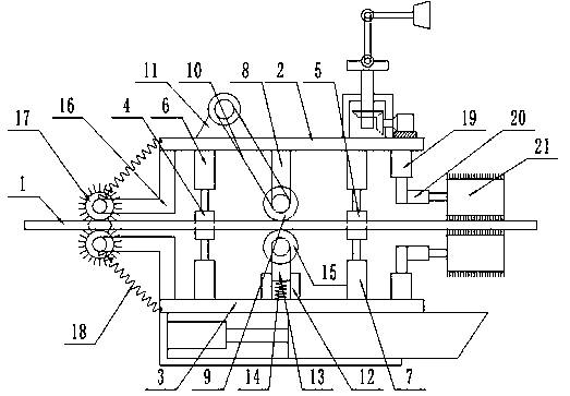
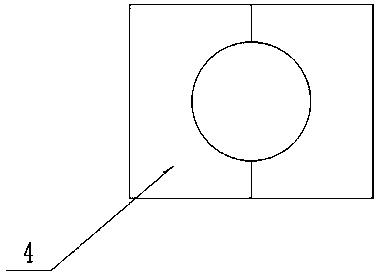
[0025] like Figure 1 to Figure 4 As shown, this specific embodiment adopts the following technical solutions: a power transmission line obstacle removal device, including: a power transmission line 1, and also includes an upper mounting plate 2, a lower mounting plate 3, a first guide seat 4, a second guide seat 5, Upper air pressure rod 6, lower air pressure rod 7, driving wheel mounting rod 8, driving wheel 9, belt 10, first motor 11, outer tube 12, inner tube 13, first spring 14, driven wheel 15, L-shaped bar 16, Sweeping wheel 17, second spring 18, first hydraulic cylinder 19, second hydraulic cylinder 20, clearing roller 21, collecting device and viewing device; the upper mounting plate 2 and the lower mounting plate 3 are respectively arranged on the power transmission line 1 The upper and lower ends; the first guide seat 4 and the second guide seat 5 are slidably connected to the power transmission line 1; the upper surfaces of the first guide seat 4 and the second gui...


PUM


Abstract

The invention discloses an obstacle removing device of a transmission line, includes an upper mounting plate, a lower mounting plate, a first guide seat, a second guide seat, an upper pneumatic lever,a lower pneumatic lever, a drive wheel mounting lever, a drive wheel, a belt, a first motor, an outer tube, an inner tube, a first spring, a driven wheel, an L-shaped lever, a sweeping wheel, a second spring, a first hydraulic cylinder, a second hydraulic cylinder, a barrier clearing roller, a collecting device and a viewing device; The utility model has the advantages of reasonable and simple structure, low production cost and convenient installation, and can effectively carry out barrier-clearing treatment on the transmission line by setting the barrier-clearing roller and the cleaning wheel, and has high cleaning efficiency, thereby solving the difficult problems in the background technology; and the utility model has the advantages of simple structure, low production cost and convenient installation. The invention is provided with a collecting device, which can collect the sundries on the cleaned transmission line to prevent the sundries from falling down and cause the hidden danger to the personnel. The invention also provides a viewing device, which can remotely view the working process, and the camera angle on the viewing device can be arbitrarily adjusted.

Description

technical field [0001] The invention relates to the technical field of power transmission lines, in particular to a power transmission line obstacle removal device. Background technique [0002] The transmission line is realized by using a transformer to boost the electric energy generated by the generator, and then connecting it to the transmission line through control equipment such as a circuit breaker. Structural forms, transmission lines are divided into overhead transmission lines and cable lines. [0003] The overhead transmission line is composed of line towers, wires, insulators, line fittings, guy wires, tower foundations, grounding devices, etc., and is erected above the ground. According to the nature of the transmission current, power transmission is divided into AC transmission and DC transmission. In the 1880s, DC transmission was first successfully realized. However, because the voltage of DC transmission was difficult to continue to increase under the tec...

Claims


Application Information

Patent Timeline
Patent Type & Authority Applications(China)
IPC IPC(8): H02G1/02
CPCH02G1/02
Inventor 高志明李艳王爱萍吕静以尚雨葳王傲高嘉成于伟张芝艳王月田骐玮田广寿刘忠谊周璐王渌于丽萍张雁
Owner STATE GRID SHANDONG ELECTRIC POWER CO LONGKOU POWER SUPPLY CO
Learn More