A micro rotating mechanism based on shape memory alloy

A technology of memory alloy and rotating mechanism, which is applied to motors, generators/motors, and electrical components that apply thermal effects, and can solve problems such as troublesome installation, inability to complete control tasks, and difficulty in realizing motor drive methods

Pending Publication Date: 2019-01-15
苏州微加测试仪器有限公司
View PDF0 Cites 4 Cited by
  • Summary
  • Abstract
  • Description
  • Claims
  • Application Information

AI Technical Summary

Problems solved by technology

[0003] This type of motor-driven rotating mechanism has the advantages of fast speed and high strength, but the disadvantage is that the mechanism is complicated, the required installation space is large, and the installation is troublesome. It is impossible to complete the control task in a place with a small space, and ther

Method used


Image

  • A micro rotating mechanism based on shape memory alloy
  • A micro rotating mechanism based on shape memory alloy
  • A micro rotating mechanism based on shape memory alloy

Examples


Embodiment 1

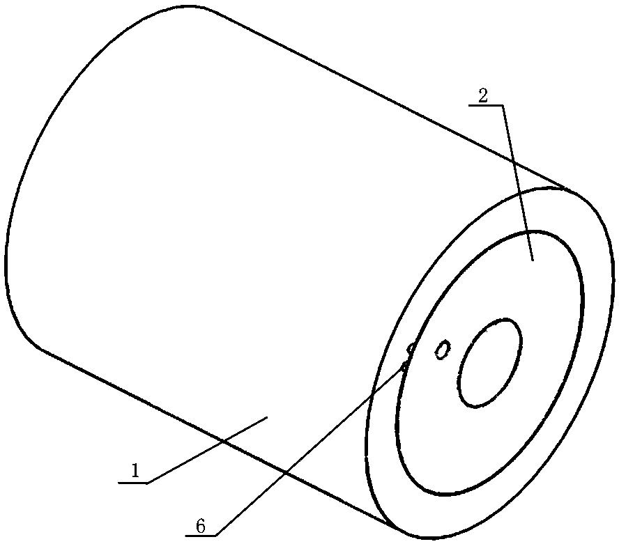
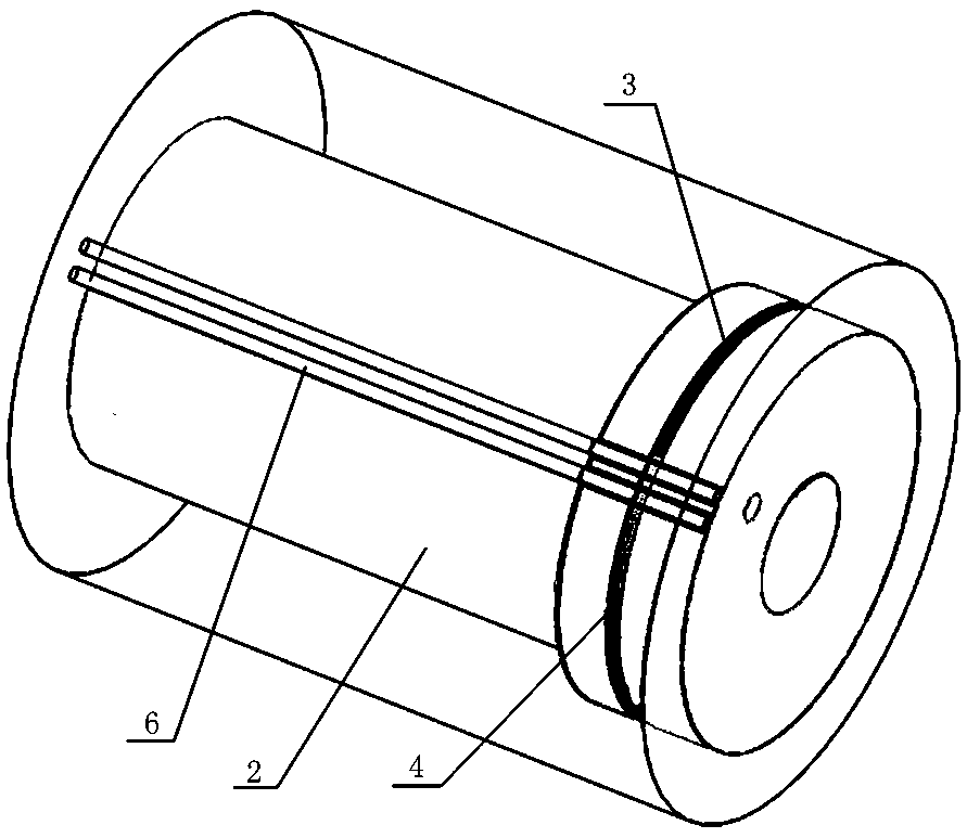
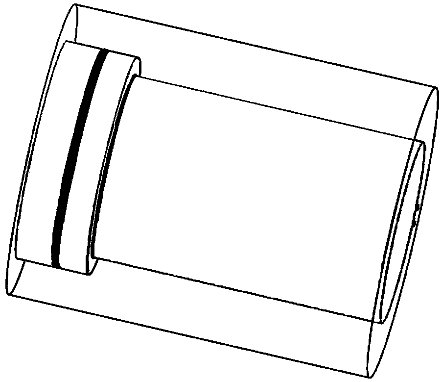
[0026] Embodiment one: see Figure 1 to Figure 3 As shown, a micro rotating mechanism based on a shape memory alloy is mainly composed of a fixed sleeve 1 and a rotating shaft 2. The surface of the rotating shaft 2 is provided with a circumferentially arranged installation groove, and the first wire 3 and the second wire are respectively arranged in the groove. Wire 4, the first end of the first wire 3 and the first end of the second wire 4 are respectively fixed on the rotating shaft and the distance between the two fixed points is less than 5% of the circumference of the rotating shaft, the first wire 3 and the second wire 4 are respectively facing away from the rotating shaft 2, and are respectively drawn out and fixed through the fixed sleeve 1, so that the first wire 3 and the second wire 4 are in a state of opposite pull; the first wire 3 is for working in A shape memory alloy wire in a shape memory state, the second wire material 4 is a shape memory alloy wire in a supe...


PUM


Abstract

The invention discloses a micro rotating mechanism based on shape memory alloy, consisting mainly of a fixed sleeve and a rotating shaft, characterized in that: A first wire and a second wire are respectively arranged on the outer surface of the rotating shaft along the circumferential direction, The first end of the first wire material and the first end of the second wire material are fixed on the rotating shaft respectively and the distance between the two fixing points is less than 5% of the circumference of the rotating shaft. The first wire material and the second wire material are respectively rotated around the rotating shaft backward and led out and fixed through a fixing sleeve so that the first wire material and the second wire material are in a pulled state. The first wire is ashape memory alloy wire working in a shape memory state, and the second wire is a shape memory alloy wire in a superelastic state; A constant current power supply is connected between the two ends ofthe first wire. The invention is suitable for completing small-range rotation in narrow space, and can be applied to medical operation, micro-mechanism control and the like. Easy to control the specific position of the rotation, and no operating noise.

Description

technical field [0001] The invention relates to a rotation drive mechanism, in particular to a miniature rotation mechanism for realizing small-scale rotation in a small space. Background technique [0002] A rotating mechanism is a device that enables the driven mechanism to complete a certain rotation or twisting action, from a first position relative to a fixed object to a second position. The rotation mechanism is used in many occasions. For example, the rotation of the mechanical arm is generally controlled by the servo motor to rotate the joint gear, and the rotation range is generally judged by the coaxial photoelectric encoder installed on the servo motor; another example is the monitoring camera. Angle adjustment, the rotation of the motor drives the gear mechanism to rotate the viewing angle of the camera to obtain the desired monitoring picture; another example is the prosthesis for the disabled, in order to help people who have lost their arms complete their arm ...

Claims


Application Information

Patent Timeline
IPC IPC(8): H02N10/00
CPCH02N10/00
Inventor 张进峰张丰彦
Owner 苏州微加测试仪器有限公司
Why Eureka
Try Eureka