
Knee joint prosthesis and control method thereof

A knee joint and prosthetic technology, applied in the field of knee joint prosthesis and control, can solve the problems of bulkiness, large size, complex structure, etc., and achieve the effect of good user experience, high reliability, and simple structure

Pending Publication Date: 2019-01-18
SHENZHEN INST OF ADVANCED TECH +1
View PDF13 Cites 0 Cited by
  • Summary
  • Abstract
  • Description
  • Claims
  • Application Information

AI Technical Summary

Problems solved by technology

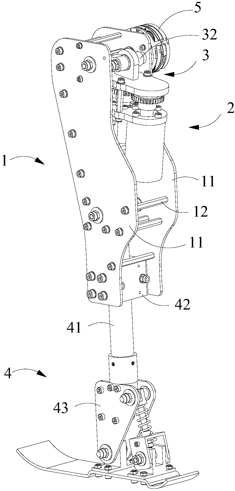
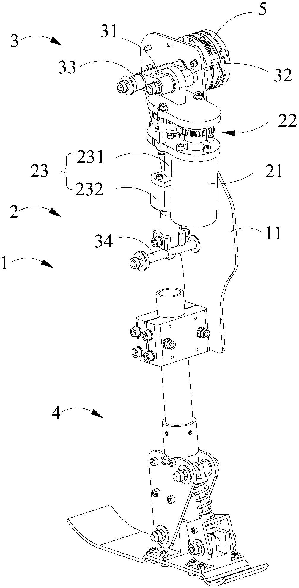
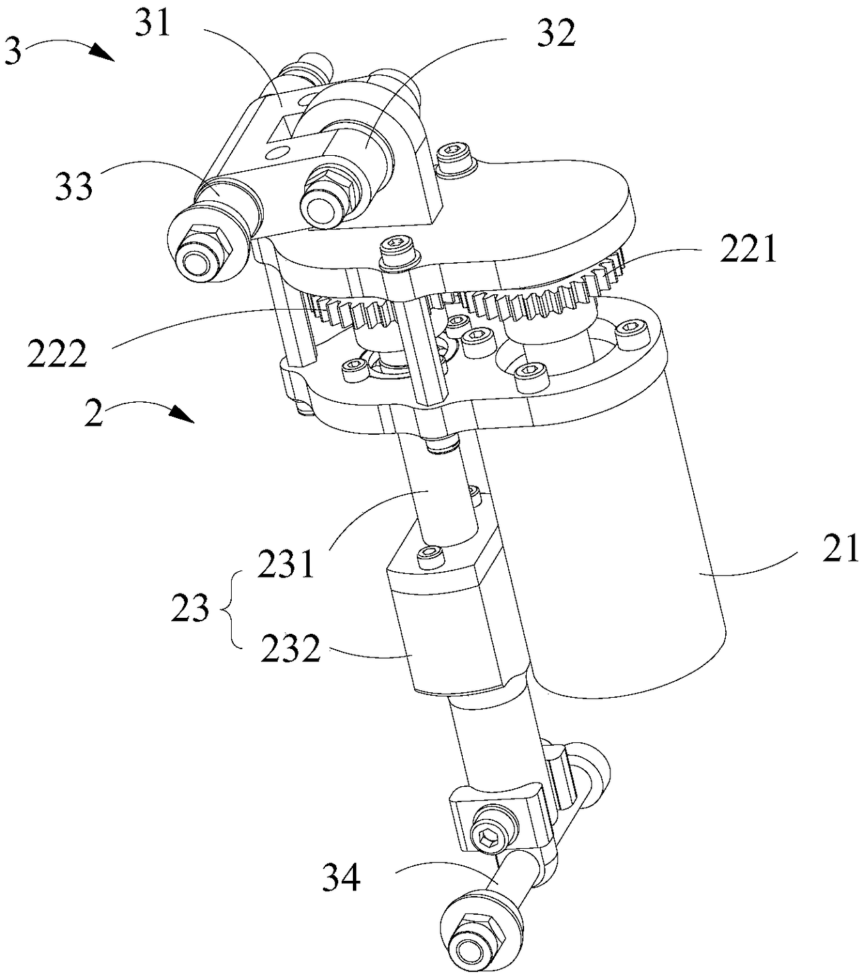
[0003] The knee joint prosthesis in the prior art usually only uses the motor as the power source, and the elastic force generated by the elastic deformation of the spring resists the actions of the user in different walking modes. The deformation of the spring cannot really match the motion of the knee joint with the motion of the natural walking state

Method used


Image

  • Knee joint prosthesis and control method thereof
  • Knee joint prosthesis and control method thereof
  • Knee joint prosthesis and control method thereof

Examples


Embodiment Construction

[0037] In order to make the technical problems solved by the present invention, the technical solutions adopted and the technical effects achieved clearer, the technical solutions of the embodiments of the present invention will be further described in detail below in conjunction with the accompanying drawings. Obviously, the described embodiments are only the technical solutions of the present invention. Some, but not all, embodiments. Based on the embodiments of the present invention, all other embodiments obtained by those skilled in the art without making creative efforts belong to the protection scope of the present invention.

[0038] In the description of the present invention, unless otherwise clearly specified and limited, the terms "connected", "connected" and "fixed" should be understood in a broad sense, for example, it can be a fixed connection, a detachable connection, or an integrated ; It can be a mechanical connection or an electrical connection; it can be a d...


PUM


Abstract

The invention discloses a knee joint prosthesis and a control method, and relates to the technical field of the knee joint prosthesis. The knee joint prosthesis comprises a calf assembly; And a powerpush rod assembly, wherein one end of the power push rod assembly is rotatably connected with the lower leg assembly, the other end of the power push rod assembly is rotatably connected with the firstend of the connecting member, and the second end of the connecting member is rotatably connected with the lower leg assembly; By varying the distance between the two ends of the power push rod assembly, the lower leg assembly can be driven to rotate about the power push rod assembly. The knee joint prosthesis has simple structure and high reliability, and can realize natural walking state. The control method adopts the knee joint prosthesis, and can automatically adjust different walking modes according to the needs of the user, so that the user experience is better.

Description

technical field [0001] The invention relates to the technical field of knee joint prosthesis, in particular to a knee joint prosthesis and a control method. Background technique [0002] After lower limb amputation due to factors such as trauma and disease, wearing an appropriate prosthetic system is the key to assisting the amputee to achieve functional rehabilitation and return to daily life and society. For patients with lower limb amputations, the purpose of installing prostheses is not only to replace the walking function, but more importantly, to simulate normal human joint movements in order to achieve the most natural gait. In the lower limb prosthesis system, the knee joint is the most important component, and its performance directly affects the overall performance of the knee prosthesis. According to the control mode of the lower limb prosthesis, the lower limb prosthesis system in the prior art can be divided into two types: passive prosthesis (or unpowered pros...

Claims


Application Information

Patent Timeline
Patent Type & Authority Applications(China)
IPC IPC(8): A61F2/64A61F2/70A61F2/60A61F2/66
CPCA61F2/60A61F2/64A61F2/66A61F2/68A61F2250/0058A61F2002/701A61F2002/607A61F2002/6614
Inventor 李光林黄品高魏文昊卢煜程陈泽添黄博俊于文龙高超
Owner SHENZHEN INST OF ADVANCED TECH
Learn More