A two-finger manipulator based on one-way transmission
A one-way transmission and manipulator technology, applied in the field of machinery, can solve problems such as difficult fine work and large volume, and achieve the effects of reducing production difficulty, high transmission efficiency, and low resistance
- Summary
- Abstract
- Description
- Claims
- Application Information
AI Technical Summary
Problems solved by technology
Method used
Image
Examples
Embodiment 1
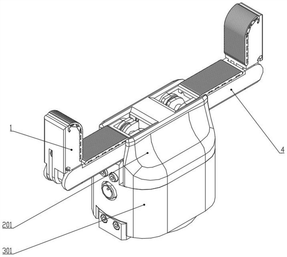
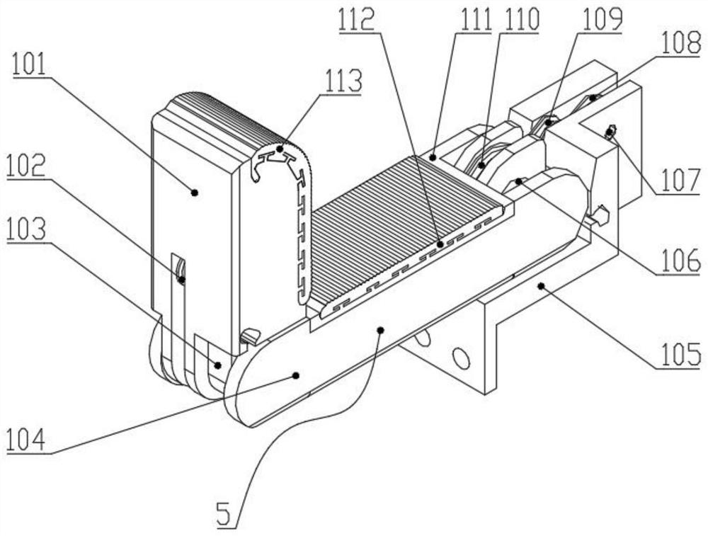
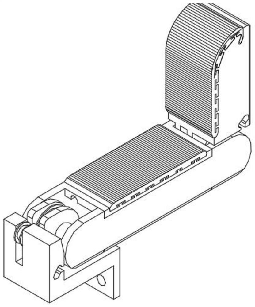
[0052] Such as Figure 1-8The shown two-finger manipulator based on one-way transmission includes a base, and finger bases 105 are respectively fixed on both sides of the base. 4 are relatively arranged; the left finger 1 and the right finger 4 both include a far knuckle 101, and the far knuckle 101 is hingedly connected with the proximal knuckle 5 through the distal knuckle joint shaft, and the proximal knuckle 5 is connected to the finger base through the proximal knuckle joint shaft 106 105 is hingedly connected; the far knuckle 101 and the proximal knuckle 5 are hingedly connected by the interphalangeal joint shaft; the proximal knuckle shaft 106 is fixed with the proximal joint pulley 110; the interphalangeal joint shaft is fixed with the distal joint pulley 6, and A distal knuckle pulley 102 is connected to the shaft on the knuckle 101; a middle pulley 108 is connected to the shaft on the finger base 105;
[0053] A rotating power device is installed on the base, and th...
Embodiment 2
[0065] Such as Figure 9 As shown, in order to minimize the driving force F of the driving rope, thereby reducing the driving power of the motor, the volume of the device and the cost, the following improvements are made:
[0066] f=f 1 or f 2 ; f 1 Indicates the restoring force of the returning spring, f 2 Indicates the restoring force of the flexible elastic band; F indicates the driving force of the driving rope; r 11 Indicates the radius of the rope wheel of the proximal joint pulley; r 21 Indicates the radius of the rope wheel of the far joint pulley; q 1 Indicates the bending angle of the proximal knuckle, q 2 Indicates the bending angle of the distal knuckle; l 3 Indicates the change in length of the driving rope; r 12 Represents the radius of the convex ring 1061 on the proximal knuckle shaft 106; r 22 Indicates the radius of the convex ring 1061 on the shaft of the far knuckle joint; l 2 Indicates the length variation of the synergistic elastic band; r 13 I...
PUM
 Abstract
Description
Claims
Application Information
 - R&D
- Intellectual Property
- Life Sciences
- Materials
- Tech Scout
- Unparalleled Data Quality
- Higher Quality Content
- 60% Fewer Hallucinations
Browse by: Latest US Patents, China's latest patents, Technical Efficacy Thesaurus, Application Domain, Technology Topic, Popular Technical Reports.
© 2025 PatSnap. All rights reserved.Legal|Privacy policy|Modern Slavery Act Transparency Statement|Sitemap|About US| Contact US: help@patsnap.com


