Kitchen knife grinding machine

A technology for grinding machines and kitchen knives, which is applied in the direction of grinding workpiece supports, other manufacturing equipment/tools, manufacturing tools, etc. It can solve the problems of inconvenient kitchen knife movement, affecting vegetable cutting, troublesome operation, etc.

Active Publication Date: 2019-01-18
嘉兴市迅程信息技术有限公司
View PDF5 Cites 2 Cited by
  • Summary
  • Abstract
  • Description
  • Claims
  • Application Information

AI Technical Summary

Problems solved by technology

[0002] When cooking in the kitchen, the dishes must be cut with a kitchen knife and cleaned before frying. However, the long-term use of the kitchen knife will have a blunt effect on the cutting of the vegetables. The kitchen knife needs to be polished regularly. Usually, people hold the kitchen knife on the polishing stone. Grinding, because the kitchen knife needs to be moved constantly, it is easy to cut people's hands and affect the subsequent grinding, and after a certain period of time, you need to stop grinding and pour water on the kitchen knife, which is troublesome to operate, so people wear gloves to avoid cuts, and need Another person helps to pour water, so the gloves are not convenient for moving the kitchen knife

Method used


Image

  • Kitchen knife grinding machine
  • Kitchen knife grinding machine

Examples


Embodiment 1

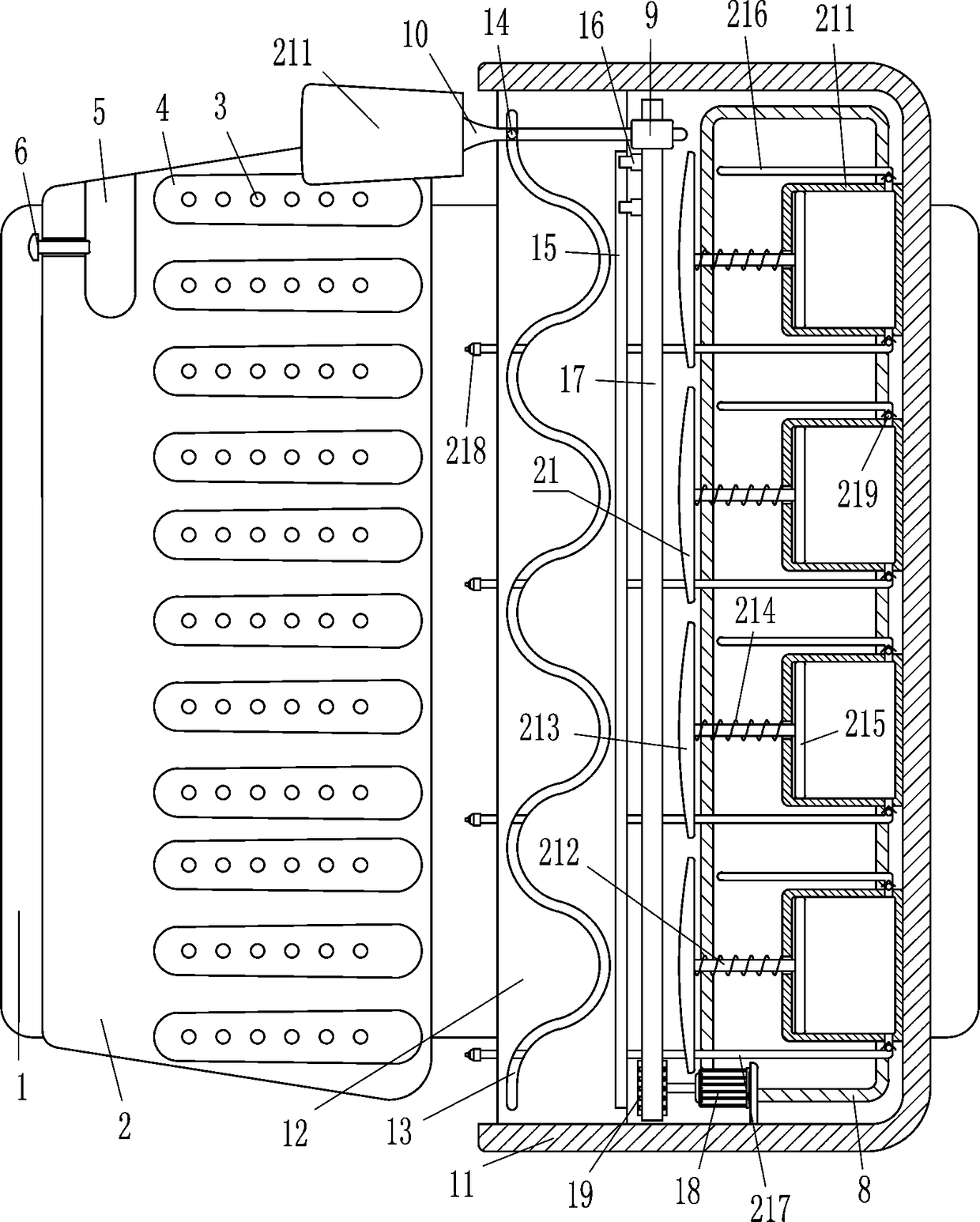
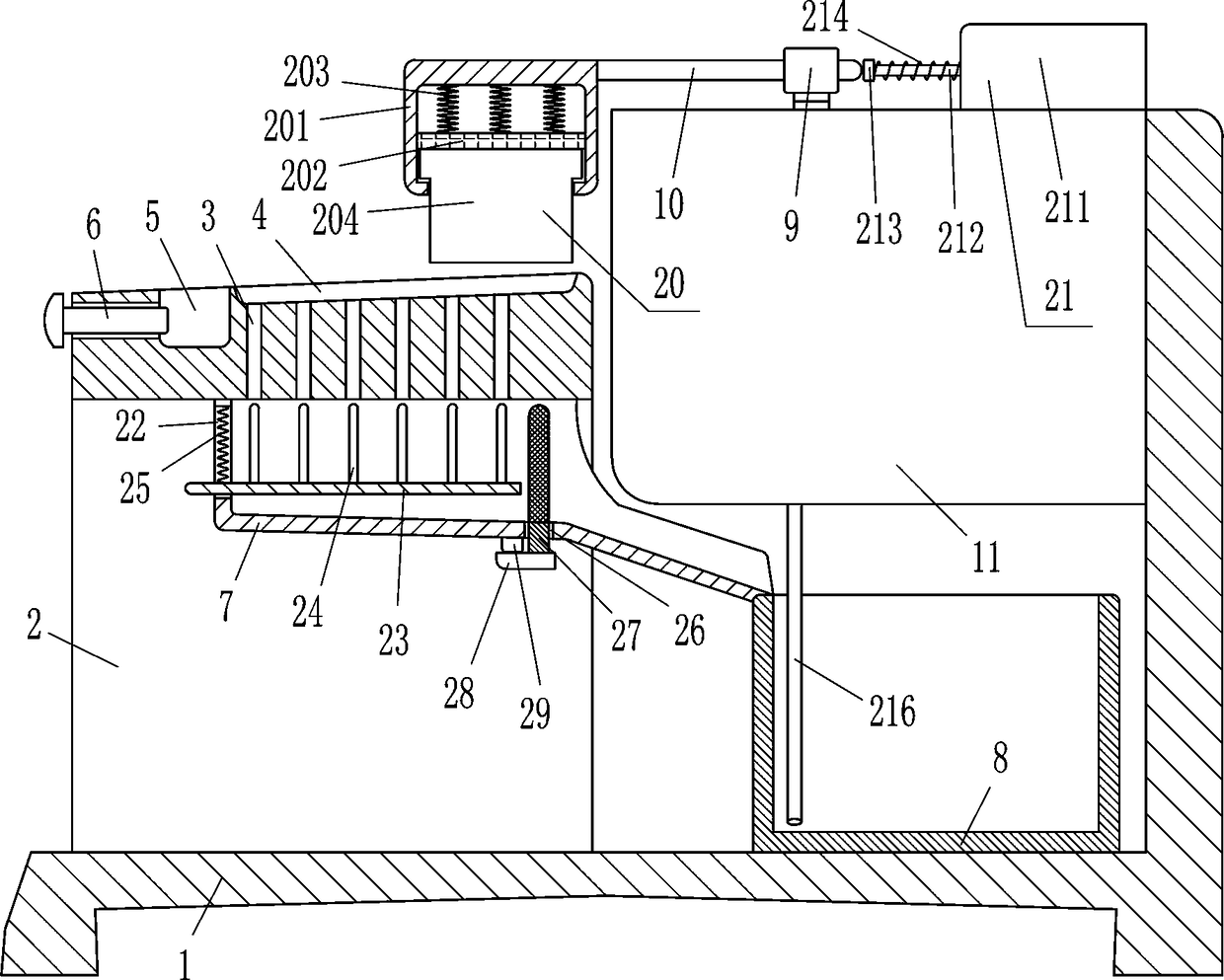
[0020] A kitchen knife grinder, such as Figure 1-2As shown, it includes L-shaped base 1, n-shaped plate 2, fastening bolt 6, lower hopper 7, collection frame 8, guide sleeve 9, cross bar 10, u-shaped plate 11, horizontal plate 12, roller 14, horizontal Slider 16, rack 17, driving motor 18, gear 19 and grinding device 20, the right side of the inner bottom of the L-shaped base 1 is provided with a collection frame 8 for collecting water, and the n-shaped plate 2 is installed on the left side of the inner bottom of the L-shaped base 1 On the side, the middle of the top of the n-type plate 2 is fixedly connected with a lower hopper 7 that can discharge water. The through hole 3 in the lower hopper 7 has a groove 4 on the right side of the outer top of the n-type plate 2, the groove 4 communicates with the inside of the through hole 3, and the left side of the outer top of the n-type plate 2 has a placement groove for placing a kitchen knife 5. The fastening bolt 6 that can fix ...

Embodiment 2

[0022] A kitchen knife sharpener such as Figure 1-2 As shown, it includes L-shaped base 1, n-shaped plate 2, fastening bolt 6, lower hopper 7, collection frame 8, guide sleeve 9, cross bar 10, u-shaped plate 11, horizontal plate 12, roller 14, horizontal Slider 16, rack 17, driving motor 18, gear 19 and grinding device 20, the right side of the inner bottom of the L-shaped base 1 is provided with a collection frame 8 for collecting water, and the n-shaped plate 2 is installed on the left side of the inner bottom of the L-shaped base 1 On the side, the middle of the top of the n-type plate 2 is fixedly connected with a lower hopper 7 that can discharge water. The through hole 3 in the lower hopper 7 has a groove 4 on the right side of the outer top of the n-type plate 2, the groove 4 communicates with the inside of the through hole 3, and the left side of the outer top of the n-type plate 2 has a placement groove for placing a kitchen knife 5. The fastening bolt 6 that can fi...

Embodiment 3

[0025] A kitchen knife sharpener such as Figure 1-2 As shown, it includes L-shaped base 1, n-shaped plate 2, fastening bolt 6, lower hopper 7, collection frame 8, guide sleeve 9, cross bar 10, u-shaped plate 11, horizontal plate 12, roller 14, horizontal Slider 16, rack 17, driving motor 18, gear 19 and grinding device 20, the right side of the inner bottom of the L-shaped base 1 is provided with a collection frame 8 for collecting water, and the n-shaped plate 2 is installed on the left side of the inner bottom of the L-shaped base 1 On the side, the middle of the top of the n-type plate 2 is fixedly connected with a lower hopper 7 that can discharge water. The through hole 3 in the lower hopper 7 has a groove 4 on the right side of the outer top of the n-type plate 2, the groove 4 communicates with the inside of the through hole 3, and the left side of the outer top of the n-type plate 2 has a placement groove for placing a kitchen knife 5. The fastening bolt 6 that can fi...


PUM


Abstract

The invention relates to a grinding machine, in particular to a kitchen knife grinding machine. The to-be-solved technical problem is to provide a more convenient kitchen knife grinding machine capable of replacing manual grinding of a kitchen knife, avoiding incised wound and spraying water onto the kitchen knife while the kitchen knife is grinded. The kitchen knife grinding machine comprises anL-shaped base, an n-shaped plate, a fastening bolt, a discharging hopper, a collecting frame, a guide sleeve, a transverse bar, a u-shaped plate, a transverse plate, a roller, a horizontal sliding block, a rack, a driving motor and the like; the right side of the inner bottom of the L-shaped base is provided with the collecting frame used for collecting water, the n-shaped plate is arranged at theleft side of the inner bottom of the L-shaped base, and the discharging hopper capable of discharging the water is fixedly connected to the middle of the inner top of the n-shaped plate. The kitchenknife grinding machine has the advantages that the kitchen knife is placed on the n-shaped plate to be in contact with grinding stone, and the driving motor is started, so that the grinding stone canmove left and right and move back and forth to grind the kitchen knife, and a person does not need to hold and continually move the kitchen knife for grinding, thereby avoiding the situation that grinding is affected due to the fact that the hand is cut.

Description

technical field [0001] The invention relates to a grinder, in particular to a kitchen knife grinder. Background technique [0002] When cooking in the kitchen, the vegetables must be cut and cleaned with a kitchen knife before frying. However, the long-term use of the kitchen knife will dull the cutting of the vegetables, so the kitchen knife needs to be polished regularly. Usually people hold the kitchen knife on the grinding stone. Grinding, because the kitchen knife needs to move continuously, it is easy to cut people's hands and affect the subsequent grinding, and after a certain period of grinding, it is necessary to stop grinding and pour water on the kitchen knife, which is troublesome to operate, so people wear gloves to avoid cuts, and need to Another person helped to pour the water, so the gloves were inconvenient for the movement of the kitchen knife. SUMMARY OF THE INVENTION [0003] In order to overcome the disadvantage that the kitchen knife needs to be cont...

Claims


Application Information

Patent Timeline
Patent Type & Authority Applications(China)
IPC IPC(8): B24B3/54B24B41/06
CPCB24B3/546B24B41/06
Inventor 廖敏珍
Owner 嘉兴市迅程信息技术有限公司
Why Eureka
Try Eureka