Hydroelectric generation apparatus with cleaning function

A power generation equipment and water conservancy technology, which is applied in the field of hydropower generation, can solve problems such as reducing the service life of hydroelectric generators, blocking cooling vents, and circuit damage, and achieves the effects of improving practicability and functionality, expanding the protection range, and avoiding high temperature damage

Inactive Publication Date: 2018-12-11
SHENZHEN BEIYOUTONG NEW ENERGY TECH DEV CO LTD
View PDF7 Cites 1 Cited by
  • Summary
  • Abstract
  • Description
  • Claims
  • Application Information

AI Technical Summary

Problems solved by technology

[0003] Hydroelectric generators are a common type of hydroelectric power generation equipment. Small hydroelectric generators are widely used in mountainous areas, but there are still some deficiencies in the actual use of existing hydroelectric generators. For example, due to lack of regular maintenance, hydroelectric generators It is easy to accumulate fallen leaves, dust and other impurities in the heat dissipation hole of the heat dissipation hole. These impurities will block the heat dissipation hole and affect the discharge of heat inside the hydroelectric generator, which may cause damage to the hydroelectric generator and reduce the service life of the hydroelectric generator. In addition, the hydroelectric generator sometimes Damaged by animals, some animals will cause damage to the circuit, thereby affecting the normal transmission of electricity, these problems have greatly reduced the practicality and functionality of existing hydropower generation equipment

Method used


Image

  • Hydroelectric generation apparatus with cleaning function
  • Hydroelectric generation apparatus with cleaning function
  • Hydroelectric generation apparatus with cleaning function

Examples


Embodiment Construction

[0030] The present invention is described in further detail now in conjunction with accompanying drawing. These drawings are all simplified schematic diagrams, which only illustrate the basic structure of the present invention in a schematic manner, so they only show the configurations related to the present invention.

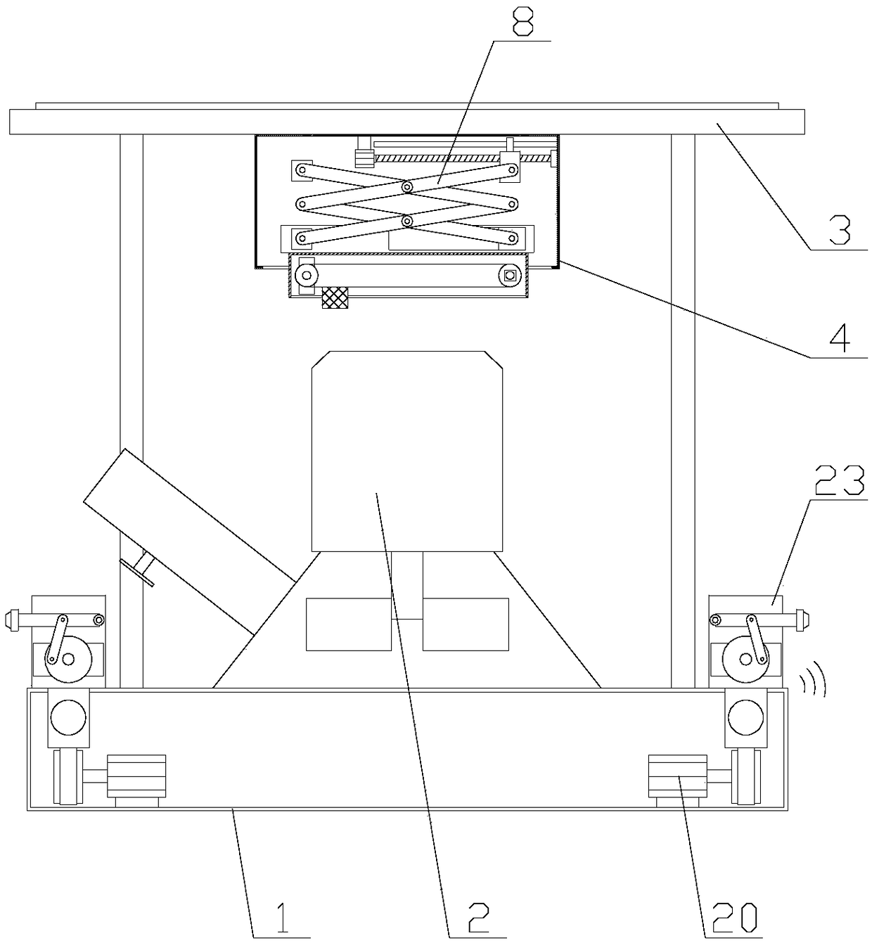
[0031] Such as figure 1 As shown, a hydroelectric power generation equipment with a cleaning function includes a base 1, a power generating device 2 and a roof 3, the power generating device 2 is arranged above the base 1, and the roof 3 is horizontally arranged above the power generating device 2 , also includes a cleaning mechanism and an expulsion mechanism, the cleaning mechanism is arranged under the top plate 3, there are two expulsion mechanisms, and the two expulsion mechanisms are respectively arranged on both sides of the power generation device 2;

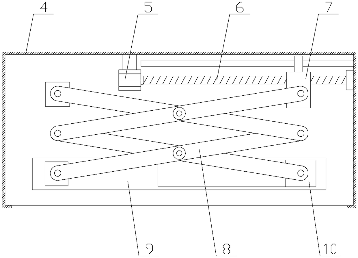
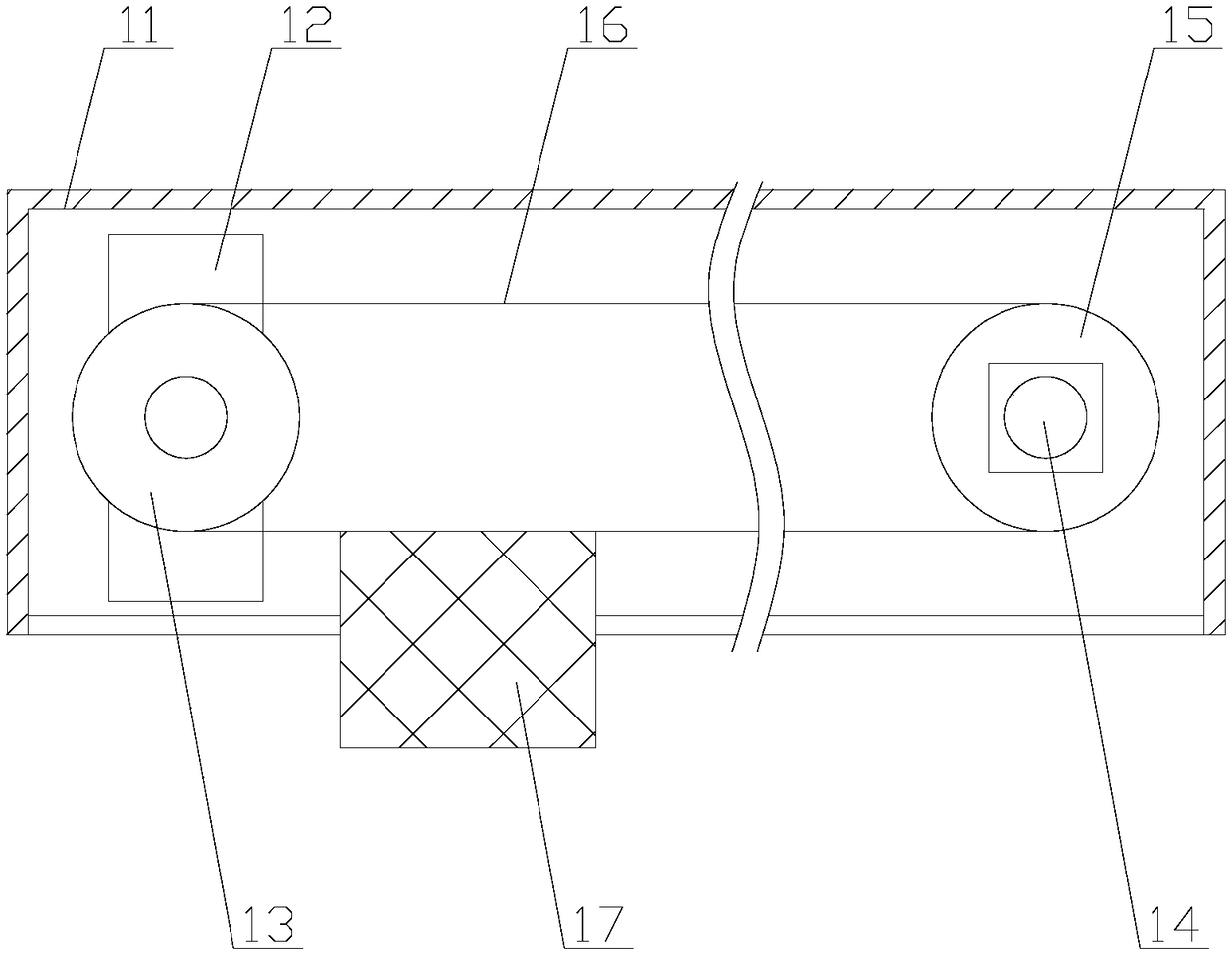
[0032] Through the cleaning mechanism, the lifting and moving of the cleaning block 17 can be contro...


PUM


Abstract

The invention relates to a hydroelectric generation apparatus with a cleaning function, comprising a base, a power generator and a top plate, as well as a cleaning mechanism and expelling mechanisms.The cleaning mechanism includes a lifting component and a cleaning component; the lifting component includes a housing and a telescopic unit; the cleaning component includes a driving chamber and a cleaning unit. Each expelling mechanism includes a moving component and a spraying component. The cleaning mechanism herein can clean impurities on air holes, thereby preventing influence upon interiorheat dissipation due to air hole blocking; damage of a hydroelectric generator due to high temperature is avoided, the service life of the hydroelectric generator is extended. The expelling mechanismsallow nozzles to spray water columns to animals for expelling, damage to the hydroelectric generation apparatus due to the approaching animals is prevented, normal delivery of power is guaranteed, and the hydroelectric generation apparatus is more practical and functional.

Description

technical field [0001] The invention relates to the field of hydropower generation, in particular to a hydropower generation device with cleaning function. Background technique [0002] Hydropower generation uses water energy mainly as potential energy stored in water bodies. When the water flows through the water turbine, the water turbine is driven by the water flow to rotate, and the water turbine drives the generator to generate electricity. The mechanical energy is converted into electrical energy, and then the electricity is sent to the user through power transformation and power transmission and distribution equipment. [0003] Hydroelectric generators are a common type of hydroelectric power generation equipment. Small hydroelectric generators are widely used in mountainous areas, but there are still some deficiencies in the actual use of existing hydroelectric generators. For example, due to lack of regular maintenance, hydroelectric generators It is easy to accumu...

Claims


Application Information

Patent Timeline
Patent Type & Authority Applications(China)
IPC IPC(8): F03B13/00F03B11/08F03B11/00H02K9/02A01M29/00
CPCA01M29/00F03B11/00F03B11/08F03B13/00H02K9/02Y02E10/20
Inventor 刘殿坤
Owner SHENZHEN BEIYOUTONG NEW ENERGY TECH DEV CO LTD
Why Eureka
Try Eureka