Solar photovoltaic panel power generation equipment with self-cleaning function

A technology of solar photovoltaic panels and power generation equipment, which is applied in the field of solar energy, can solve problems such as easily affecting power generation effects and equipment damage, and achieve the effects of preventing damage, improving utilization, and avoiding cleaning dead ends

Inactive Publication Date: 2020-09-18
金扬晨
View PDF0 Cites 9 Cited by
  • Summary
  • Abstract
  • Description
  • Claims
  • Application Information

AI Technical Summary

Problems solved by technology

[0004] The purpose of the present invention is to provide a solar photovoltaic panel power generation equipment with self-cleaning function to solve the problem that in the prior art, the solar power generation equipment is installed outdoors, and dust, rain and snow water are likely to affect the power generation effect and cause damage to the equipment. question

Method used


Image

  • Solar photovoltaic panel power generation equipment with self-cleaning function
  • Solar photovoltaic panel power generation equipment with self-cleaning function
  • Solar photovoltaic panel power generation equipment with self-cleaning function

Examples


Embodiment 1

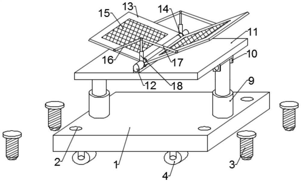
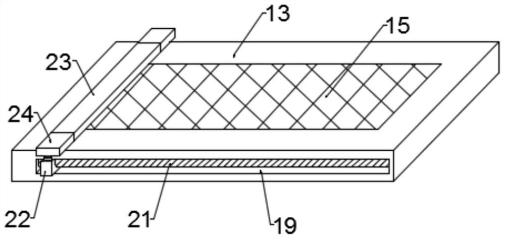
[0035] Such as figure 1 and image 3 As shown, the embodiment of the present invention provides a solar photovoltaic panel power generation device with self-cleaning function, the power generation device includes a base 1, a fixed assembly is arranged on the base 1, and foldable wheels are installed on the bottom of the base 1; The upper surface of the base 1 is connected to the mounting plate 11 through a tilting mechanism, two solar photovoltaic panels 15 are arranged above the mounting plate 11, and the two solar photovoltaic panels 15 are clamped in the installation frame 13, and the two installation The frames 13 are all rotated and mounted on the fixed rod 12 through the rotating ring 14, and a folding mechanism is connected between the two mounting frames 13; a self-cleaning mechanism is installed on the upper surface of the mounting frame 13, and the self-cleaning mechanism includes a cleaning assembly. The cleaning assembly is installed between the rotating assemblie...

Embodiment 2

[0049] Such as Figure 1~2 As shown, in yet another embodiment provided by the present invention, the fixing assembly includes fixing bolts 3 installed in fixing holes 2 , and the fixing holes 2 are opened around the base 1 .

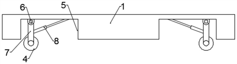
[0050] Further, the bottom of the base 1 is provided with a storage cavity 5; the foldable wheel includes a mounting base 6, the mounting base 6 is fixed on the top of the storage cavity 5, and the mounting base 6 is rotatably installed with a connection Rod 7, the bottom of the connecting rod 7 is equipped with a pulley 4 through the axle; the side wall of the connecting rod 7 is connected with a hydraulic telescopic push arm 8, and the other end of the hydraulic telescopic push arm 8 is installed in the storage chamber 5 top.

[0051] When it is necessary to drive the device to move, start the hydraulic telescopic push arm 8 to extend, control the connecting rod 7 to go vertically downward, and the pulley 4 touches the ground, and the rolling of the ...


PUM


Abstract

The invention is suitable for the technical field of solar energy, and provides solar photovoltaic panel power generation equipment with a self-cleaning function. The power generation equipment comprises a base which is provided with a fixed assembly, and the bottom of the base is provided with foldable wheels. The upper surface of the base is connected with a mounting plate through an inclinationmechanism, two solar photovoltaic panels are arranged above the mounting plate, the two solar photovoltaic panels are both clamped in mounting frames, the two mounting frames are both rotationally mounted on a fixing rod through rotating rings, and a folding mechanism is connected between the two mounting frames; a self-cleaning mechanism is installed on the upper surface of the mounting frame and comprises a cleaning assembly, the cleaning assembly is installed between rotating assemblies, the two ends of each rotating assembly are connected with sliding assemblies, and the sliding assemblies are installed in grooves formed in the side wall of the mounting frame. The purpose of scraping dust, rainwater and snow water is achieved through the self-cleaning mechanism.

Description

technical field [0001] The invention belongs to the technical field of solar energy, and in particular relates to a solar photovoltaic panel power generation device with self-cleaning function. Background technique [0002] With the development of the economy and the progress of the society, people have put forward higher and higher requirements for energy. The traditional thermal power energy needs to burn fossil fuels such as coal and oil, which not only has limited reserves and is facing depletion, but also produces a large amount of carbon dioxide during combustion. And sulfur oxides, destroying the earth's environment. The ideal energy source needs to meet the two conditions of being abundant, inexhaustible, and safe and clean. Solar energy is the most ideal energy source. It is not only inexhaustible, but also safe and reliable. [0003] Among them, solar photovoltaic power generation refers to a power generation method that directly converts light energy into electric...

Claims


Application Information

Patent Timeline
Patent Type & Authority Applications(China)
IPC IPC(8): H02S20/30H02S30/20H02S40/10B08B1/04B08B13/00F24S30/425F24S40/20
CPCB08B1/04B08B13/00F24S30/425F24S40/20H02S20/30H02S30/20H02S40/10Y02E10/47Y02E10/50
Inventor 金扬晨
Owner 金扬晨
Why Eureka
Try Eureka