A waste rubber regeneration device

A recycling device and waste rubber technology, applied in the field of recycled rubber, can solve the problems of affecting the concentration of the slurry pool, affecting the surrounding environment, and exhaust gas not up to standard

Active Publication Date: 2022-01-18
徐州托普新材料有限公司
View PDF9 Cites 0 Cited by
  • Summary
  • Abstract
  • Description
  • Claims
  • Application Information

AI Technical Summary

Problems solved by technology

[0005] In order to make up for the deficiencies of the existing technology, to solve the problem of regenerating waste rubber with desulfurization tanks, a large amount of waste gas will be generated. The waste gas contains rubber powder particles and organic pollutants. People will use water and limestone slurry to treat colloidal particles and organic pollution. However, after using clean water to remove colloidal particles, the exhaust gas will carry a large amount of water into the slurry tank, which will affect the concentration in the slurry tank, affect the removal of organic pollutants, cause the exhaust gas to fail to meet the standard, and affect the surrounding environment. , a waste rubber regeneration device proposed by the present invention

Method used


Image

  • A waste rubber regeneration device
  • A waste rubber regeneration device
  • A waste rubber regeneration device

Examples


Embodiment 1

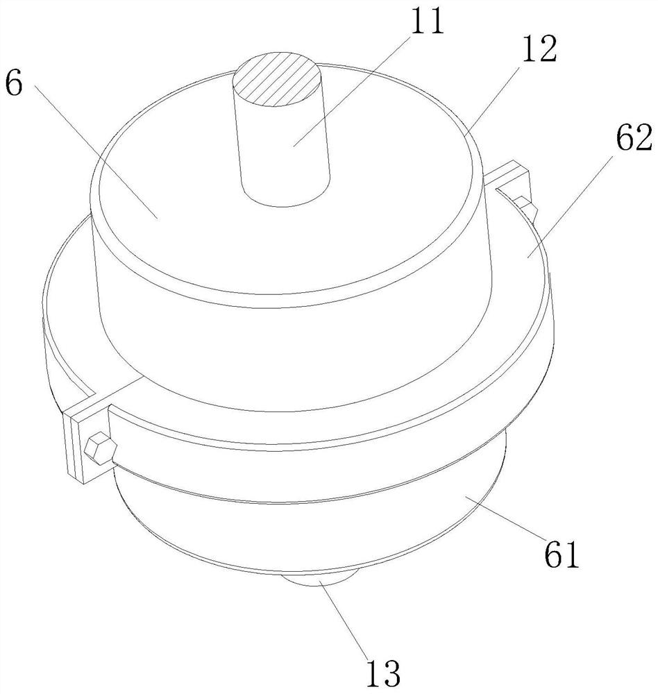
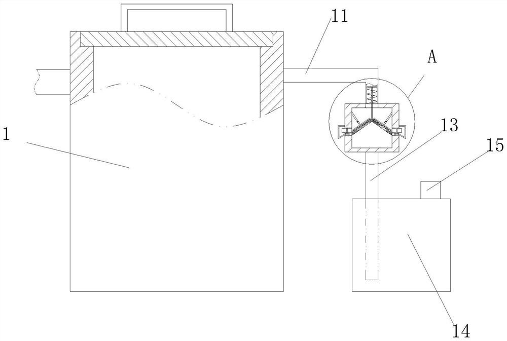
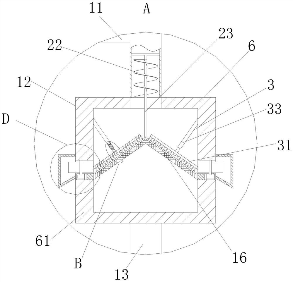
[0032] like Figure 1 to Figure 7 As shown, a waste rubber recycling device according to the present invention includes a desulfurization tank 1; a waste gas pipe 11 is provided on the side wall of the desulfurization tank 1; the waste gas pipe 11 is L-shaped, and the bottom end of the waste gas pipe 11 is fixed Connected with a filter box 12; the bottom end of the filter box 12 is connected with a slurry tank 14 through a connecting pipe 13; the inside of the slurry tank 14 is limestone slurry, and the connecting tube 13 extends into the slurry; the slurry tank 14 is provided with Exhaust pipe 15; the filter box 12 is provided with a conical filter screen 16, and the tip of the cone is upward; in the prior art, when using the desulfurization tank 1 to regenerate the waste rubber, a large amount of waste gas will be generated, and the waste gas contains rubber Colloidal particles and organic pollutants, etc., people will use water and limestone slurry to remove impurities from...

Embodiment 2

[0042] see Figure 8As shown in Comparative Example 1, as another embodiment of the present invention, a layer of rubber layer 67 is affixed to the inner wall of the semicircular collection box 62; Connect and wrap the impurity removal tank 68, and then collect the rubber powder particles filtered by the conical filter screen 16. In order to prevent the waste gas from escaping from the contact between the semicircular collection box 62 and the upper box body 6 and the lower box body 61, the semicircle A rubber layer 67 is fixedly attached to the side wall of the circular collection box 62, which can increase the sealing effect and prevent exhaust gas from escaping.

[0043] Working principle: The waste gas produced by the desulfurization tank 1 enters the filter box 12 through the waste gas pipe 11, and the rubber powder particles are filtered out through the conical filter screen 16, and then the filter gas is passed into the slurry pool through the connecting pipe 13 to remo...


PUM


Abstract

The invention belongs to the technical field of regenerated rubber, and specifically relates to a waste rubber regeneration device, which includes a desulfurization tank; a waste gas pipe is provided on the side wall of the desulfurization tank; the waste gas pipe is L-shaped, and the bottom end of the waste gas pipe is fixed There is a filter box; the bottom end of the filter box is connected to a slurry tank through a connecting pipe; the inside of the slurry box is limestone slurry, and the connecting pipe extends into the slurry; a conical filter is provided in the filter box, and the tip of the cone faces Above; the present invention provides a waste rubber regeneration device to solve the problem that a large amount of waste gas will be generated when using a desulfurization tank to regenerate waste rubber. The waste gas contains rubber powder particles and organic pollutants. Particles and organic pollutants are removed, but after the colloidal particles are removed with clean water, the exhaust gas will carry a large amount of water into the slurry tank, which will affect the concentration in the slurry tank, affect the removal of organic pollutants, and cause the exhaust gas to fail to meet the standard. The problem of the surrounding environment.

Description

technical field [0001] The invention belongs to the technical field of regenerated rubber, in particular to a waste rubber regenerating device. Background technique [0002] Regenerated rubber is made of waste rubber as raw material by recycling technology. The regeneration process needs to go through a desulfurization process to change the plastic state of the waste rubber particle network structure and restore its soft rubber-like structure. [0003] There are also some technical solutions on recycled rubber technology in the prior art. For example, a Chinese patent with application number 2018110657130 discloses a waste gas treatment device for the production of recycled rubber, including a storage box. The storage box The upper end of the body is provided with a ventilation assembly, and the ventilation assembly includes a ventilation pipe and a heater. A fan is installed on the other end of the ventilation pipe away from the material storage box, and a stirring assembly...

Claims


Application Information

Patent Timeline
Patent Type & Authority Patents(China)
IPC IPC(8): C08J11/10C08L17/00
CPCC08J11/10C08J2317/00Y02W30/62
Inventor 岳喜东
Owner 徐州托普新材料有限公司
Why Eureka
Try Eureka