Steel ingot forging and compacting device and using method thereof
A compacting device and steel ingot technology, applied in the field of steel ingot forging, can solve the problems of low turning and moving efficiency
- Summary
- Abstract
- Description
- Claims
- Application Information
AI Technical Summary
Problems solved by technology
Method used
Image
Examples
Embodiment 1
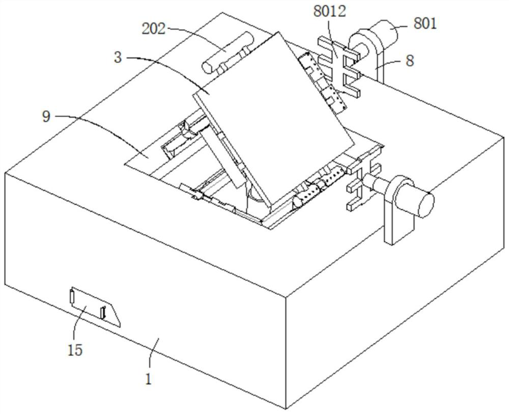
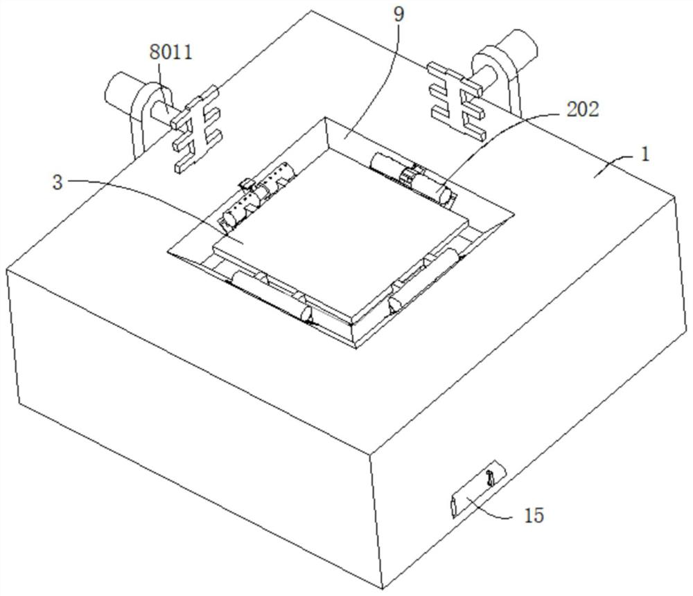
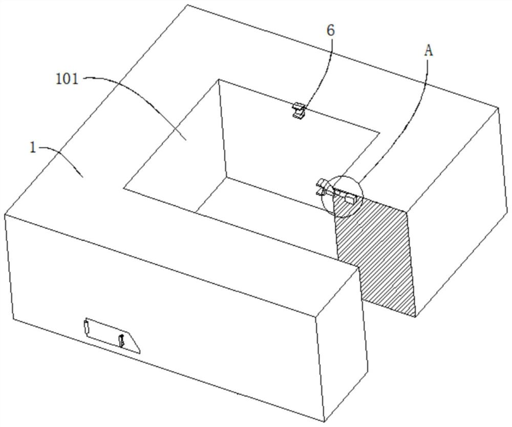
[0040] refer to Figure 1-8 , a steel ingot forging compaction device, comprising a forging table 1, the outer wall of the forging table 1 is dug with a movable groove 101, the inner wall of the movable groove 101 is connected with a square frame 1011, and the top of the square frame 1011 is connected with four brackets 2, four brackets The outer walls of the seat 2 are all dug with an arc-shaped groove 201, the inner wall of the arc-shaped groove 201 is movably connected with a fixed rod 202, the outer wall of the fixed rod 202 is connected with a connecting rod 203, and the end of the connecting rod 203 far away from the fixed rod 202 is connected with the loading table 3. A shell 4 is connected between the frame 1011 and the bottom wall of the movable groove 101, and a jacking mechanism is arranged in the shell 4, and the jacking mechanism is connected with the bottom wall of the stage 3, and the outer walls of two adjacent brackets 2 are dug with An annular groove 204, a f...
Embodiment 2
[0046] refer to Figure 1-9 , a steel ingot forging and compacting device, which is basically the same as that of Embodiment 1, furthermore, the inner wall of the movable groove 101 is also connected with an auxiliary plate 9, and the outer wall of the auxiliary plate 9 is provided with an inclined surface, and the outer wall of the inclined surface is dug to match the bracket 2 Fitting second groove 901 .
[0047] The casing 4 includes an upper casing 401 and a lower casing 402, the upper casing 401 is fixedly connected to the bottom wall of the box 1011, the lower casing 402 is fixedly connected to the bottom inner wall of the movable groove 101, and the lower casing 402 includes an upper bucket-shaped body 4021 and the lower bucket 4022, the top of the upper bucket 4021 is provided with an opening, the upper shell 401 and the upper bucket 4021 are provided with a drop tank 11, and the lower bucket 4022 and the movable tank 101 are provided with a slag collection cavity 12....
Embodiment 3
[0052] refer to Figure 1-10 , a steel ingot forging compaction device, which is basically the same as embodiment 2, furthermore, the outer wall of the fixed rod 202 is provided with evenly distributed balls 10; it is convenient to improve the convenience of pushing the steel ingot forging by the push plate 8012, so that the steel ingot forging moves relatively easy.
[0053] The invention also discloses a method for using a steel ingot forging and compacting device, comprising the following steps:
[0054] S1: After the molten steel is cast into a steel ingot, the steel ingot is placed on the stage 3, and the staff controls the hydraulic machine to forge it. First, it is first upset, pressed squarely, and drawn out the long square side and the four short sides. The long side is strong pressure, and the short side is chamfered. After the second upsetting, the short side is used to press the four-sided elongated interface to prevent the elongation at the same position after th...
PUM
 Abstract
Description
Claims
Application Information
 - R&D
- Intellectual Property
- Life Sciences
- Materials
- Tech Scout
- Unparalleled Data Quality
- Higher Quality Content
- 60% Fewer Hallucinations
Browse by: Latest US Patents, China's latest patents, Technical Efficacy Thesaurus, Application Domain, Technology Topic, Popular Technical Reports.
© 2025 PatSnap. All rights reserved.Legal|Privacy policy|Modern Slavery Act Transparency Statement|Sitemap|About US| Contact US: help@patsnap.com


