
Composite grinding device of ball screw nuts

A technology of ball screw and compound grinding, which is applied in the direction of tangent device, grinding frame, grinding bed, etc., which can solve the problem of the reduction of the coaxiality between the internal thread and outer diameter of the ball screw nut and the inapplicability of the ball screw nut , The processing device cannot adapt to the market demand, etc., to achieve the effect of reducing the installation coaxiality error, improving production efficiency, and simple structure

Active Publication Date: 2019-01-18
上海莱必泰数控机床股份有限公司
View PDF7 Cites 2 Cited by
  • Summary
  • Abstract
  • Description
  • Claims
  • Application Information

AI Technical Summary

Problems solved by technology

[0002] The traditional ball screw nut grinding method is mainly to have a separate internal thread grinder to grind the internal thread of the ball screw nut, and then change to an external grinding machine to continue grinding the outer diameter and end face of the ball screw nut, so that The relative characteristic of the grinding method is that the structure is simple, and the traditional machine tool can realize it, but it needs two equipments to complete it, and the coaxiality of the internal thread and the outer diameter of the ball screw nut will be reduced due to the secondary clamping. Highly demanding ball screw nuts are not suitable
[0003] With the rapid development of the manufacturing industry and the increase of various artificial land costs in recent years, the demand for complex and efficient processing methods is becoming stronger and stronger, so the traditional processing equipment can no longer meet the market demand.

Method used

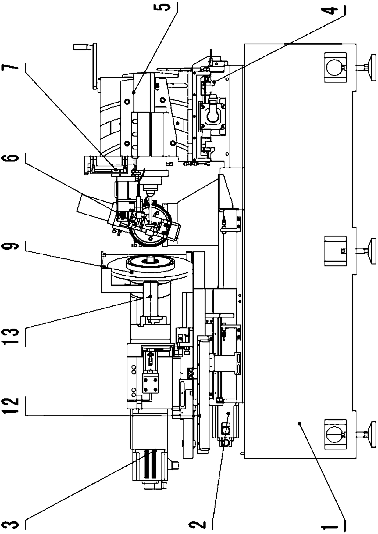
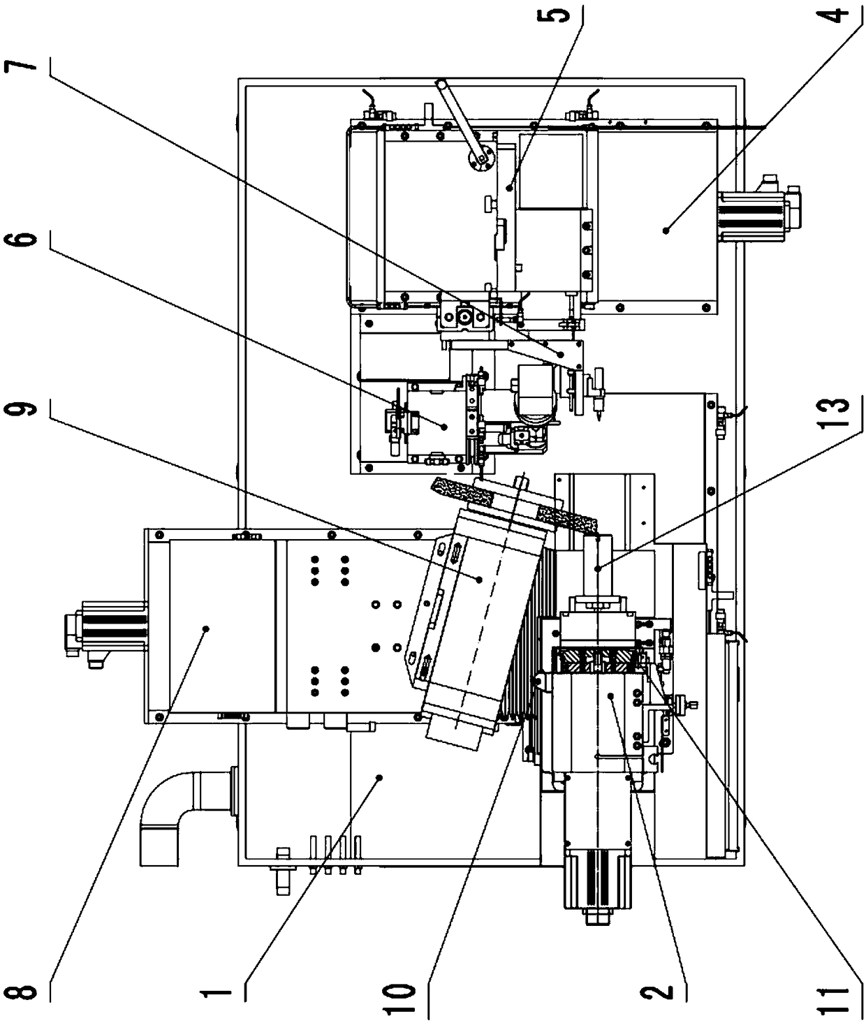

Image

  • Composite grinding device of ball screw nuts
  • Composite grinding device of ball screw nuts

Examples


Embodiment Construction

[0022] In order to make the technical means, creative features, goals and effects achieved by the present invention easy to understand, the present invention will be further described below in conjunction with specific illustrations.

[0023] see figure 1 and figure 2 , the ball screw nut compound grinding device provided by the present invention comprises a bed 1, a workpiece carriage unit 2, a workpiece drive unit 3, an internally threaded grinding wheel shaft carriage unit 4, an internally threaded grinding wheel shaft unit 5, an internally threaded grinding wheel Dressing unit 6, measuring unit 7, outer diameter end grinding wheel shaft carriage unit 8, outer diameter end grinding wheel shaft unit 9, outer diameter end grinding wheel dressing unit 10, workpiece rotary circular grating 11, workpiece carriage linear grating 12 and control box.

[0024] Bed 1, which is the installation base of the present application, is provided with workpiece carriage unit 2 on its left f...


PUM


Abstract

The invention discloses a composite grinding device of ball screw nuts. The composite grinding device comprises a lathe bed, a workpiece drive unit, an outer diameter end face grinding wheel dressingunit, an outer diameter end face grinding wheel shaft unit, an inner thread grinding wheel shaft unit, a measuring unit, a workpiece rotary circular grating and a workpiece carriage linear grating. Aworkpiece carriage unit, an outer diameter end face grinding wheel shaft carriage unit, an inner thread grinding wheel shaft carriage unit and an inner thread grinding wheel dressing unit are arrangedon the lathe bed. The measuring unit is arranged on the inner thread grinding wheel shaft unit. The workpiece rotary circular grating is arranged at the front end of the workpiece drive unit. The workpiece carriage linear grating is arranged at the front end of the workpiece carriage unit. The composite grinding device is simple in structure and convenient to operate, inner thread grinding and outer diameter grinding of the ball screw nuts are integrated, all auxiliary time in the machining process can be shortened to be minimal, the mounting coaxiality errors of the outer diameters and innerthreads of the ball screw nuts are greatly reduced, the production efficiency of the lathe bed is greatly improved, and the production cost can be greatly reduced.

Description

technical field [0001] The invention relates to a grinding device, in particular to a compound grinding device for ball screw nuts. Background technique [0002] The traditional ball screw nut grinding method is mainly to have a separate internal thread grinder to grind the internal thread of the ball screw nut, and then change to an external grinding machine to continue grinding the outer diameter and end face of the ball screw nut, so that The relative characteristic of the grinding method is that the structure is simple, and the traditional machine tool can realize it, but it needs two equipments to complete it, and the coaxiality of the internal thread and the outer diameter of the ball screw nut will be reduced due to the secondary clamping. Highly demanding ball screw nuts are not suitable. [0003] With the rapid development of the manufacturing industry and the increase of various artificial land costs in recent years, the demand for complex and efficient processing...

Claims


Application Information

Patent Timeline
Patent Type & Authority Applications(China)
IPC IPC(8): B24B7/16B24B27/00B24B41/02B24B41/06B24B49/12B24B49/03B23G1/36
CPCB23G1/36B24B7/16B24B27/0076B24B41/02B24B41/06B24B49/03B24B49/12Y02P70/10
Inventor 周华奚健沈雨张燕李艳
Owner 上海莱必泰数控机床股份有限公司
Learn More