
Novel tunnel lining segment mold

A technology for lining segments and molds, applied in the direction of molds, mold fixing devices, mold auxiliary parts, etc., can solve the problems of large number of mold bolts, inconvenient cleaning for construction personnel, poor mold size adjustment, etc., to achieve easy demoulding and opening and closing of molds , to avoid changes in dimensional accuracy, to ensure the effect of structural stability

Inactive Publication Date: 2019-01-18
江苏丰和隧道设备有限公司
View PDF8 Cites 6 Cited by
  • Summary
  • Abstract
  • Description
  • Claims
  • Application Information

AI Technical Summary

Problems solved by technology

[0003] The existing tunnel segment mold production mainly adopts three vibrating methods: manual insertion vibrating, integral vibrating and attached vibrating. Among them, manual inserting vibrating takes a long time to vibrate, the production efficiency is low, and the labor intensity is high; the vibration quality Human factors are high, easy to fluctuate, and the mold size is poorly adjustable; the integral vibrator has a large number of bolts, the structure is cumbersome, the operation is intensive, time-consuming, laborious, and the mold size is poorly adjusted; the attached vibrator adopts a flexible structure and the structure is relatively simple , but the mold structure is unstable. After opening and closing, the dimensional accuracy changes greatly, the rubber strip at the bottom is easy to wear, and the segment forming effect at the rubber contact is poor.
[0004] In addition, the side molds, end molds and bottom molds of the existing attached vibrating mold adopt the lapping steel chamfer contact mode, resulting in dead angles inside the mold, which is not convenient for construction personnel to clean, and the vibration effect is poor

Method used


Image

  • Novel tunnel lining segment mold
  • Novel tunnel lining segment mold
  • Novel tunnel lining segment mold

Examples


Embodiment Construction

[0046] Embodiments of the technical solutions of the present invention will be described in detail below in conjunction with the accompanying drawings. The following examples are only used to illustrate the technical solutions of the present invention more clearly, and therefore are only examples, rather than limiting the protection scope of the present invention.

[0047] It should be noted that, unless otherwise specified, the technical terms or scientific terms used in this application shall have the usual meanings understood by those skilled in the art to which the present invention belongs.

[0048] In the description of the present application, it should be understood that the terms "center", "longitudinal", "transverse", "length", "width", "thickness", "upper", "lower", "front", " Back", "Left", "Right", "Vertical", "Horizontal", "Top", "Bottom", "Inner", "Outer", "Clockwise", "Counterclockwise", "Axial", The orientation or positional relationship indicated by "radial"...


PUM


Abstract

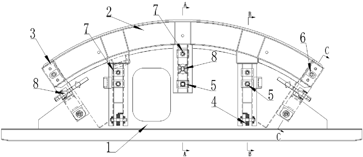
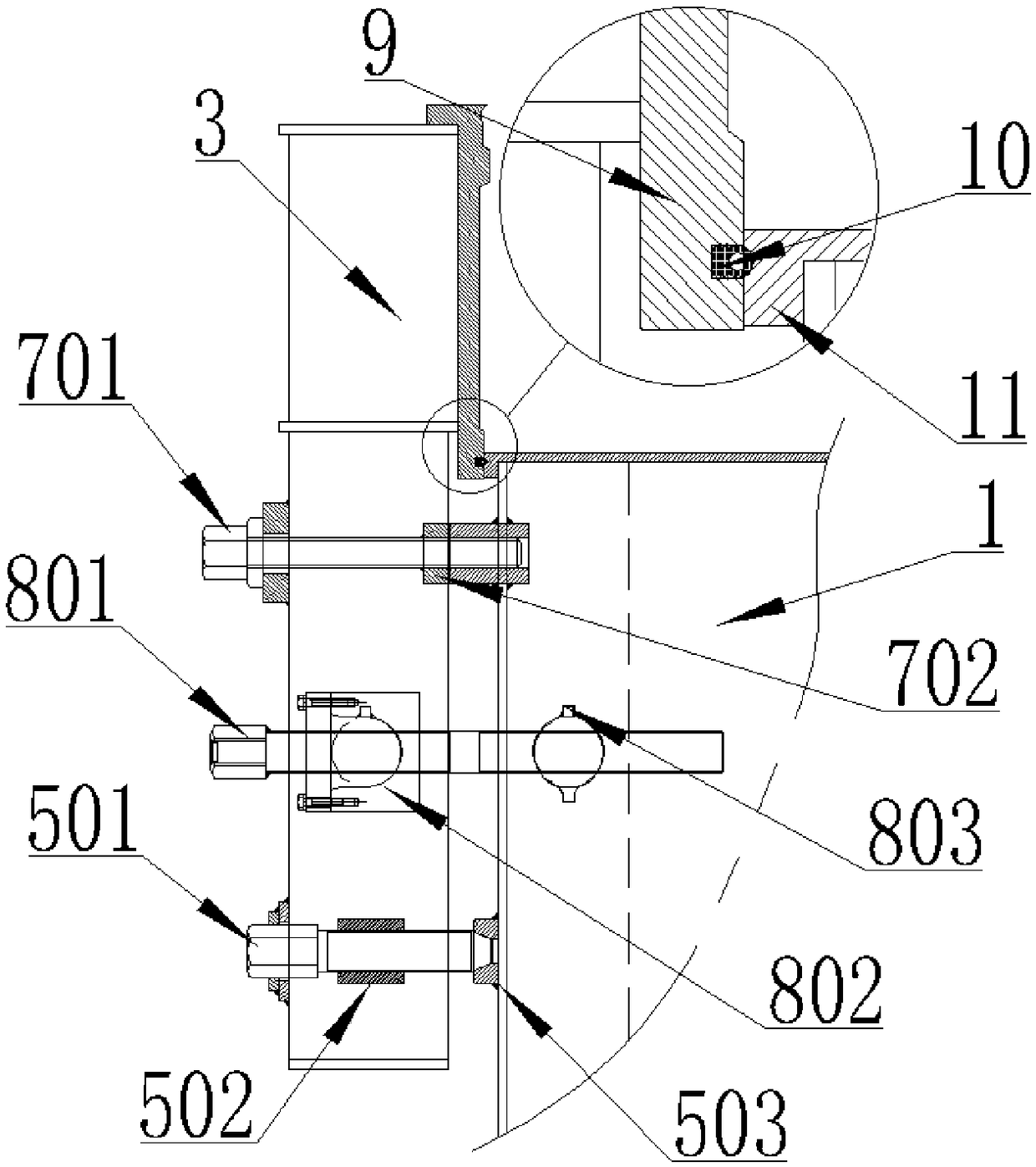
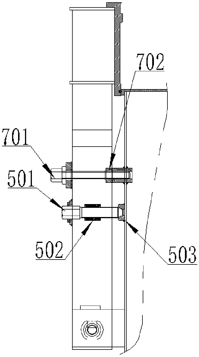
The invention discloses a novel tunnel lining segment mold. The novel tunnel lining segment mold comprises a bottom mold body, end mold bodies symmetrically arranged on the two sides of the bottom mold body and side mold bodies symmetrically arranged at the top of the bottom mold body. The bottom ends of the side mold bodies and the bottom ends of the end mold bodies are connected with the bottommold body through hinges, the side mold bodies and the end mold bodies are positioned on the bottom mold body through adjustable conical positioning devices, the side mold bodies and the end mold bodies are positioned through conical positioning devices, the side mold bodies, the bottom mold body and the end mold bodies are locked through locking devices, and mold starting devices are arranged between the side mold bodies and the bottom mold body as well as between the end mold bodies and the bottom mold body. The novel tunnel lining segment mold is accurate in positioning, stable in structureand high in precision, no clearing dead corners exist, and the novel tunnel lining segment mold can adapt to attachment type vibration and improve product quality.

Description

technical field [0001] The invention relates to the technical field of tunnel segment production, in particular to a novel tunnel lining segment mold. Background technique [0002] Shield construction is the safest and most effective construction method for subway construction, and has been gradually adopted by construction units. The most critical part of shield construction is tunnel lining segment; with the rapid development of shield construction, the demand for tunnel lining segment is increasing; tunnel lining segment is the main concrete prefabricated component of subway shield construction, its production The process is more complicated, and the requirements are becoming more and more serious. Among them, the pouring of each shield segment is mainly completed by means of segment molds. [0003] The existing tunnel segment mold production mainly adopts three vibrating methods: manual insertion vibrating, integral vibrating and attached vibrating. Among them, manual ...

Claims


Application Information

Patent Timeline
Patent Type & Authority Applications(China)
IPC IPC(8): B28B7/02
CPCB28B7/0002B28B7/0014B28B7/02
Inventor 王曙钱凤亮叶娟
Owner 江苏丰和隧道设备有限公司
Learn More