Marine drag reduction mechanism

A marine and guiding mechanism technology, applied in the direction of hull, ship construction, ships, etc., can solve problems other than drag reduction

Inactive Publication Date: 2019-01-18
LANZHOU UNIVERSITY OF TECHNOLOGY
View PDF4 Cites 0 Cited by
  • Summary
  • Abstract
  • Description
  • Claims
  • Application Information

AI Technical Summary

Problems solved by technology

[0003] The existing ship drag reduction methods all realize the ship drag reduction function from the perspective of reducing navigation resistance. These measures have achieved obvious drag reduction effects, but this is not the whole method of drag reduction

Method used


Image

  • Marine drag reduction mechanism

Examples


Embodiment Construction

[0015] The present invention will be further described below in conjunction with accompanying drawing:

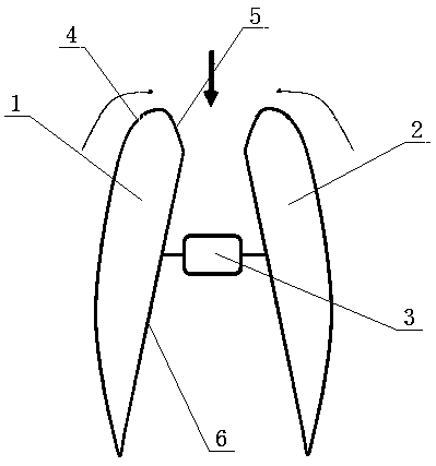
[0016] Such as figure 1 Shown: the present invention comprises left airfoil type lifting mechanism, right airfoil type lifting mechanism and adjustment guiding mechanism, described left airfoil type lifting mechanism, right airfoil type lifting mechanism are two symmetrical airfoil type lifting mechanisms, the one of two described airfoil type lifting mechanisms The center is fixedly arranged on the adjustment guide mechanism for adjusting the opening angle of the left airfoil lift mechanism and the right airfoil lift mechanism. When the fluid velocity changes, the airfoil lift mechanism can adjust the opening angle to adjust the force generated by the drag reducing device.

[0017] Further, the two airfoil lift mechanisms are composed of a lift section, a diversion section and an expansion section, the outside of the fluid direction end of the airfoil lift mechanism is th...


PUM

PropertyMeasurementUnit
Angleaaaaaaaaaa

Abstract

The invention discloses a marine drag reduction mechanism, which includes a left wing lifting mechanism, a right wing type lifting mechanism and an adjusting guide mechanism, wherein the left wing type lifting mechanism and the right wing type lifting mechanism are two symmetrical airfoil lifting mechanisms, and the two airfoil lifting mechanisms are fixedly arranged between the two airfoil lifting mechanisms and an adjusting guide mechanism for adjusting the opening angle of the left wing type lifting mechanism and the right wing type lifting mechanism. In accordance with that prior art, thedrag reduction principle of the invention is fundamentally different from the existing surface drag reduction and pressure differential drag reduction, Its typical characteristic is that the kinetic energy carried by the fluid is utilized to convert it into the static pressure energy of the driving device, so besides the power of the ship itself, there is also the input of the fluid energy, so theeffect of drag reduction of the ship hull can be seen from the overall performance of the dynamic performance.

Description

technical field [0001] The invention relates to a mechanical device for reducing drag of a hull, in particular to a drag reducing mechanism for a ship. Background technique [0002] Reducing the navigation resistance of the hull in water is of great significance for reducing ship power and improving energy utilization. The resistance suffered by a ship in water can be divided into two categories: frictional resistance and differential pressure resistance. All kinds of ways to reduce the drag of ships at home and abroad are carried out from these two aspects. In terms of reducing surface frictional resistance, research at home and abroad has focused on non-smooth wall drag reduction and super-hydrophobic surface materials. The soil-contacting parts of agricultural machinery are coupled with bionic surfaces; the bionic surface drag-reducing structure of paddy field boat-type machinery with the publication number CN203840742U is developed from surface characteristics and mate...

Claims


Application Information

Patent Timeline
IPC IPC(8): B63B1/28
CPCB63B1/28
Inventor 余建平苏栋栋付佳王鹏超
Owner LANZHOU UNIVERSITY OF TECHNOLOGY
Why Eureka
Try Eureka