Multi-dimension multi-point intelligent feeding system for products
A feeding system, multi-specification technology, applied in conveyor control devices, conveyors, conveyor objects, etc., can solve the problems of cluttered materials, low production efficiency, and large space occupation in the workshop, and achieve refined production management, The effect of improving production efficiency and simple operation
- Summary
- Abstract
- Description
- Claims
- Application Information
AI Technical Summary
Problems solved by technology
Method used
Image

Examples
Embodiment Construction
[0032] The following will be combined with Figure 1-Figure 6 The present invention is described in detail, and the technical solutions in the embodiments of the present invention are clearly and completely described. Apparently, the described embodiments are only some of the embodiments of the present invention, not all of them. Based on the embodiments of the present invention, all other embodiments obtained by persons of ordinary skill in the art without making creative efforts belong to the protection scope of the present invention.
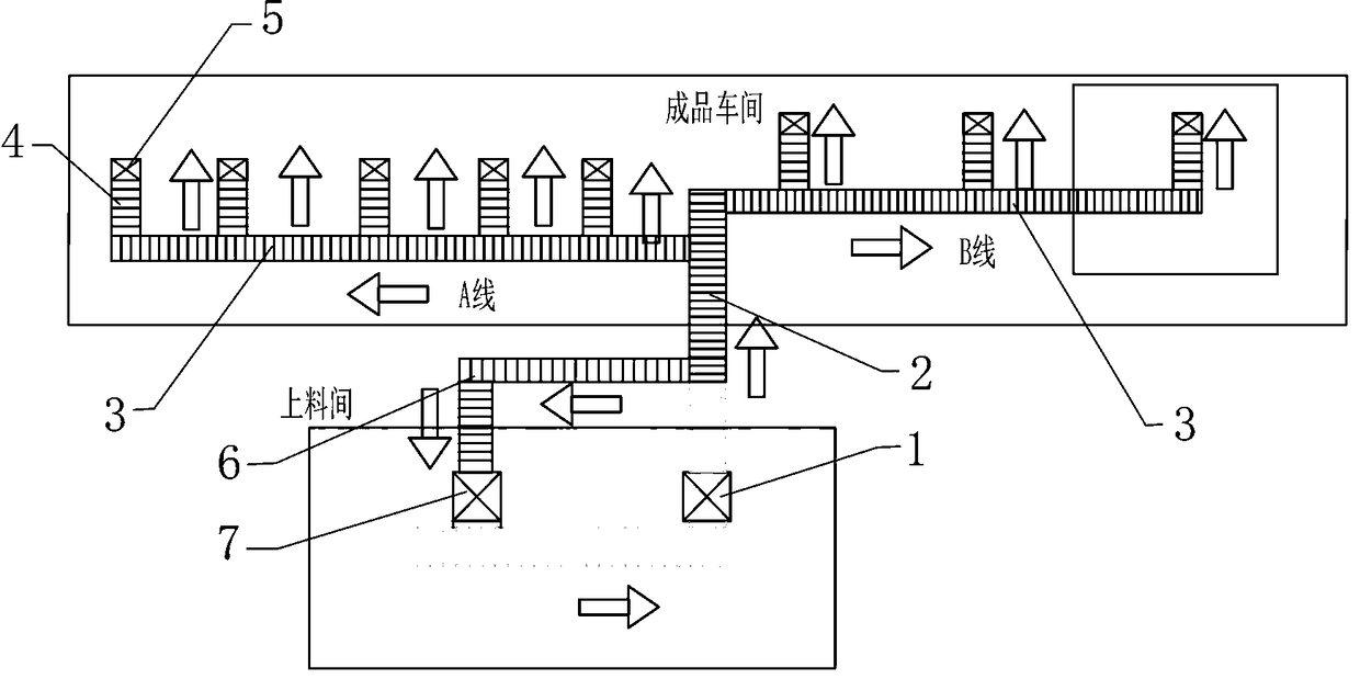
[0033] Such as Figure 1-Figure 6 As shown, the present invention provides a kind of to kind, multi-standard, multi-point intelligent feeding system here, including
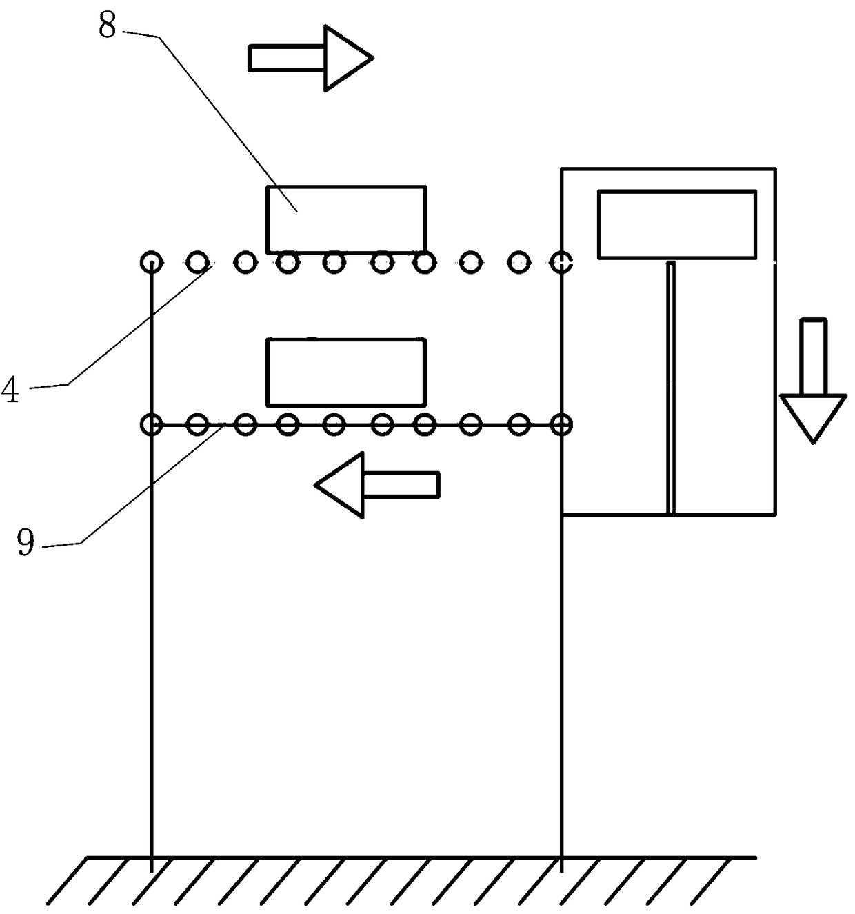
[0034] The material box 8 carrying the material has a uniquely identified barcode pasted on the side of the material box, and the barcode is pasted around the material box to facilitate scanning by the scanner;
[0035] The feeding device 1 located in the feeding workshop, whi...
PUM
 Abstract
Description
Claims
Application Information
PatSnap Eureka turns technology decisions into work you can execute. Powered by our Innovation Knowledge Graph, it runs expert workflows across engineering, life sciences, materials and intellectual property. Get your review-ready output in minutes.


