Fabricated-partition-wall connecting device and connecting method
A connecting device and assembly technology, applied in the direction of walls, building components, buildings, etc., can solve the problems of poor sound insulation effect, affecting the aesthetics, integrity and interface peeling of the interior walls of the house.
Pending Publication Date: 2019-01-18
广东华坤建设集团有限公司 +1
0 Cites 3 Cited by
AI-Extracted Technical Summary
Problems solved by technology
[0003] It should be pointed out that the prefabricated panels in the prefabricated partition wall are generally made of light materials, the rigidity of the prefabricated panels is small, and the deformation of the prefabricated panels is relatively large compared with structural components such as beams and columns.
Due to the uncoordinated deformation of the prefabricated panels in the partition...
Method used
Comprehensive above-mentioned situation can know, by above-mentioned structure design, the prefabricated partition wall connecting device of the present invention has the advantages of novel design, simple structure, convenient connection operation, and can effectively avoid the problem of peeling and cracking of partition wall connection interface and can Effectively ensure the aesthetics and integrity of the joints of the prefabricated partition wall. Under the background of developing construction industrialization as a national strategy, especially the current development of prefabricated buildings, it is an inherent need for the transformation and upgrading of the construction industry; this invention forms a new partition wall method and technology by improving the traditional partition wall connection method, It effectively solves the current prefabricated partition walls with complex construction procedures and construction difficulties caused by large manufacturing errors. At the same time, it effectively solves the problem of connection ...
Abstract
The invention discloses a fabricated-partition-wall connecting device and connecting method. A fabricated partition wall comprises a left prefabricated plate and a right prefabricated plate, steel connecting boxes are embedded into connecting-box containing grooves formed between the left prefabricated plate and the right prefabricated plate, and connecting-box cavities, left bolt holes and rightbolt boles are formed in the steel connecting boxes; left reinforced reinforcing steel bars are pre-embedded inside the left prefabricated plate, and are welded with left bolt sleeves, and left fastening bolts which are in threaded connection with the left bolt sleeves are embedded into the left bolt holes of the steel connecting boxes; right reinforced reinforcing steel bars are pre-embedded inside the right prefabricated plate, and are welded with right bolt sleeves, and right fastening bolts which are in threaded connection with the right bolt sleeves are embedded into the right bolt holesof the steel connecting boxes. The fabricated-partition-wall connecting device and connecting method have the advantages of being novel in design, simple in structure and convenient to connect and operate, can effectively solve the problem that the partition-wall joint interface is peeled and cracked, and can effectively guarantee the attractive performance and the integrality of the fabricated-partition-wall joint portion.
Application Domain
Walls
Technology Topic
RebarEngineering +1
Image
Examples
- Experimental program(1)
Example Embodiment
[0039] The present invention will be described below in conjunction with specific embodiments.
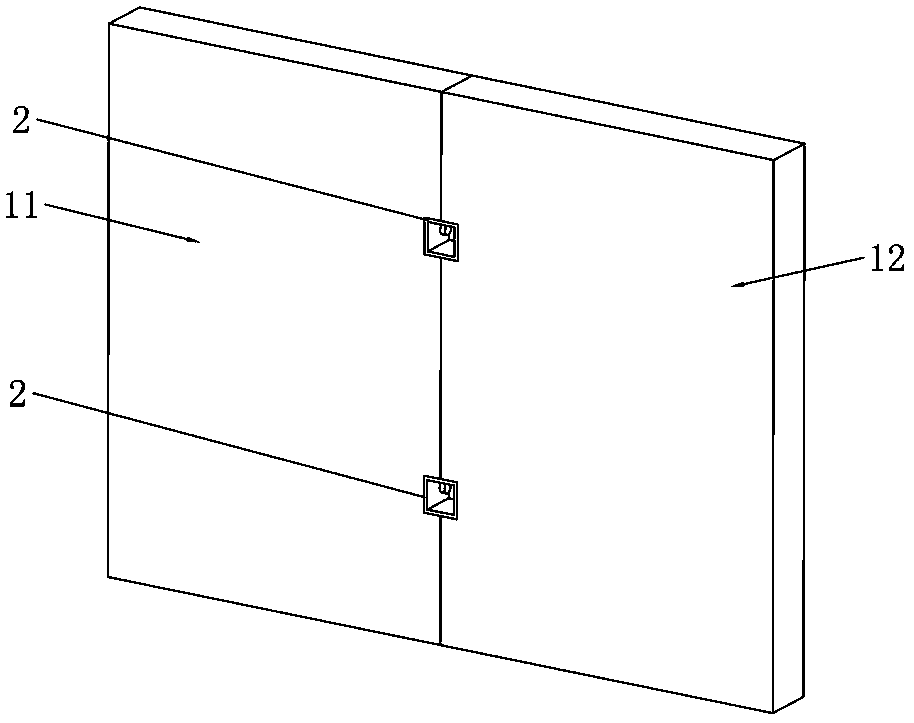
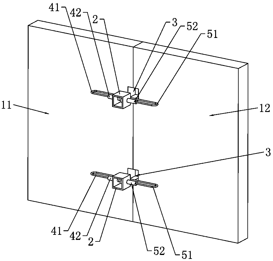
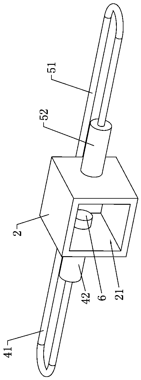
[0040] Such as Figure 1 to Figure 6 As shown, a prefabricated partition wall connecting device includes a left prefabricated plate 11 and a right prefabricated plate 12 arranged vertically, respectively, and the left prefabricated plate 11 is located at the left end of the right prefabricated plate 12 Side, the right end surface of the left prefabricated plate 11 is in contact with the left end surface of the right prefabricated plate 12, and the assembled partition wall connection device includes a steel connection box 2, and the inside of the steel connection box 2 is formed with a forward opening The left side wall of the connecting box chamber 21 is provided with a left bolt hole 22 that completely penetrates to the left, and the right side wall of the connecting box chamber 21 is provided with a right bolt that completely penetrates to the right Hole 23; the right end edge of the left prefabricated plate 11 corresponds to the steel connection box 2 with a left connection groove 111, the left end edge of the right prefabricated plate 12 corresponds to the steel connection box 2 with a right connection groove 121, and the left The side connecting groove 111 and the right connecting groove 121 are aligned left and right, and the left connecting groove 111 and the right connecting groove 121 are jointly enclosed to form a connecting box accommodating groove 3 with a shape consistent with the shape of the steel connecting box 2 and opening to the front .
[0041] Furthermore, the left side reinforcing steel bar 41 in the shape of "U" is pre-embedded inside the right end edge of the left prefabricated plate 11, and the two straight sections of the left side reinforcing steel bar 41 are arranged at intervals in the front and rear and extend horizontally along the left and right directions respectively. The right end of the front straight section of the left reinforcing steel bar 41 is welded with a left bolt sleeve 42 that is embedded in the left prefabricated plate 11 and extends horizontally along the left and right directions. The left bolt sleeve 42 is provided with The left internal threaded hole 421 extending along the axis of the left bolt sleeve 42 and opening to the right, the right end of the left bolt sleeve 42 is exposed on the left side wall of the left connecting groove 111 and the left bolt sleeve The left internal threaded hole 421 of the pipe 42 is aligned left and right with the left bolt hole 22 of the steel connection box 2. The left bolt hole 22 of the steel connection box 2 is embedded with the left fastening bolt 6, and the left side is tight The threaded end of the fixing bolt 6 is screwed into the left internal threaded hole 421 of the left bolt sleeve 42; the right end of the rear straight section of the left reinforcing steel bar 41 extends into the left side of the left prefabricated plate 11 for connection The thin position directly behind the groove 111.
[0042] Furthermore, the right side reinforcing steel bar 51 in the shape of "U" is embedded inside the left end edge of the right prefabricated plate 12, and the two straight sections of the right side reinforcing steel bar 51 are spaced apart from each other and extend horizontally along the left and right directions. , The left end of the front straight section of the right reinforcing steel bar 51 is welded with a right bolt sleeve 52 that is embedded in the right prefabricated plate 12 and extends horizontally along the left and right directions. The right bolt sleeve 52 is opened inside There is a right internal threaded hole 521 extending along the axis of the right bolt sleeve 52 and opening to the left. The left end of the right bolt sleeve 52 is exposed on the right side wall of the right connecting groove 121 and the right bolt The right internal threaded hole 521 of the sleeve 52 is aligned left and right with the right bolt hole 23 of the steel connection box 2. The right side bolt hole 23 of the steel connection box 2 is embedded with the right fastening bolt 7, the right side The threaded end of the fastening bolt 7 is screwed into the right internal threaded hole 521 of the right bolt sleeve 52; the left end of the rear straight section of the right reinforcing steel bar 51 extends to the right of the right prefabricated plate 12 The thin position directly behind the connecting groove 121.
[0043] In addition, the right end of the rear straight section of the left reinforcing steel 41 is welded with a steel sleeve 43 extending horizontally in the left and right direction. The steel sleeve 43 is located directly behind the left connecting groove 111 of the left prefabricated plate 11 Inside the position, the steel sleeve 43 is provided with a steel sleeve hole 431 extending along the axis of the steel sleeve 43 and opening to the right. The right end of the steel sleeve 43 is exposed on the right end of the left prefabricated plate 11 ; The left end of the rear straight section of the right reinforcing steel bar 51 protrudes from the left end surface of the right prefabricated plate 12, and the rebar sleeve hole 431 of the reinforcing steel sleeve 43 is aligned with the rear straight section of the right reinforcing steel bar 51. And the left end of the rear straight section of the right side reinforcing steel bar 51 is inserted into the steel bar sleeve hole 431 of the steel bar sleeve 43.
[0044] It should be explained that the left fastening bolt 6 and the right fastening bolt 7 are respectively steel bolts, the left bolt sleeve 42 and the right bolt sleeve 52 are respectively steel sleeves, and the reinforced sleeve 43 is steel casing.
[0045] Regarding the above-mentioned prefabricated partition wall connection device, the following methods can be used to realize the connection of the left prefabricated plate 11 and the right prefabricated plate 12 of the prefabricated partition wall. Specifically, a prefabricated partition wall connection method includes the following Process steps, specific:
[0046] a. Prepare and shape the left prefabricated plate 11 and the right prefabricated plate 12; for the left prefabricated plate 11, the right end edge of the left prefabricated plate 11 is formed with a left connection groove 111 and the right end edge of the left prefabricated plate 11 The left side of the reinforcing steel bar 41 is pre-embedded in the shape of a "U". The two straight sections of the left side reinforcing steel bar 41 are spaced apart from each other and extend horizontally along the left and right directions. The right end is welded with a left bolt sleeve 42 that is embedded in the left prefabricated plate 11 and extends horizontally along the left and right directions. The left bolt sleeve 42 is opened in the axial direction along the left bolt sleeve 42 The left internal threaded hole 421 that extends and opens to the right, the right end of the left bolt sleeve 42 is exposed on the left side wall of the left connection groove 111, and the right end of the rear straight section of the left reinforcing steel bar 41 is welded There is a reinforced casing 43 extending horizontally in the left and right direction. The reinforced casing 43 is located in the thin position directly behind the left connecting groove 111 of the left prefabricated plate 11. The reinforced casing 43 is provided with a reinforced casing along the inside The rebar sleeve hole 431 extends in the axial direction of 43 and opens to the right. The right end surface of the rebar sleeve 43 is exposed on the right end surface of the left prefabricated plate 11; for the right prefabricated plate 12, the left end of the right prefabricated plate 12 The right side connecting groove 121 is formed on the edge part and the right side reinforcing steel bar 51 in the shape of "U" is embedded inside the left end edge part of the right prefabricated plate 12. The two straight line sections of the right side reinforcing steel bar 51 are arranged at intervals and respectively. Extending horizontally along the left and right direction, the left end of the front straight section of the right reinforcing steel bar 51 is welded with a right bolt sleeve 52 that is embedded in the right prefabricated plate 12 and extends horizontally along the left and right direction, and the right bolt The inside of the sleeve 52 is provided with a right internal threaded hole 521 that extends along the axis of the right bolt sleeve 52 and opens to the left. The left end of the right bolt sleeve 52 is exposed to the right of the right connecting groove 121 On the side wall, the left end of the rear straight section of the right reinforcing steel bar 51 extends into the thin position directly behind the right connecting groove 121 of the right prefabricated plate 12, and the left end of the rear straight section of the right reinforcing steel bar 51 The part protrudes from the left end surface of the right prefabricated plate 12;
[0047] b. Combine the left prefabricated plate 11 and the right prefabricated plate 12 and make the right end surface of the left prefabricated plate 11 and the left end surface of the right prefabricated plate 12 contact and join together, and make the rear straight section of the right reinforcing steel bar 51 The left end is inserted into the rebar sleeve hole 431 of the rebar sleeve 43; wherein the left connection groove 111 of the left prefabricated plate 11 is aligned with the right connection groove 121 of the right prefabricated plate 12, and the left connection groove 111 and the right connecting groove 121 are jointly enclosed to form a connecting box accommodating groove 3 that opens forward;
[0048] c. Insert the steel connection box 2 into the connection box accommodating groove 3 between the left prefabricated plate 11 and the right prefabricated plate 12, and the shape of the steel connection box 2 is consistent with the shape of the connection box accommodating groove 3 The inside of the steel connecting box 2 is formed with a connecting box cavity 21 that opens forward, and the left side wall of the connecting box cavity 21 is provided with left and right internal threads that completely penetrate to the left and are connected to the left side of the left bolt sleeve 42 The left bolt holes 22 are aligned, and the right side wall of the connecting box chamber 21 is provided with a right bolt hole 23 that completely penetrates to the right and is aligned with the right internal threaded hole 521 of the right bolt sleeve 52;
[0049] d. Install the left fastening bolt 6 and the right fastening bolt 7: Put the left fastening bolt 6 into the connection box chamber 21 of the steel connection box 2 and insert the left fastening bolt 6 into the steel Make the left side bolt hole 22 of the connecting box 2, tighten the left side fastening bolt 6 and tighten the threaded end of the left side fastening bolt 6 into the left side internal threaded hole 421 of the left side bolt sleeve 42; Put the right fastening bolt 7 into the connection box cavity 21 of the steel connection box 2 and insert the right fastening bolt 7 into the right bolt hole 23 of the steel connection box 2, and tighten the right side Fasten the bolt 7 and tighten the threaded end of the right fastening bolt 7 into the right internal threaded hole 521 of the right bolt sleeve 52;
[0050] e. Pour mortar into the joint between the left prefabricated board 11 and the right prefabricated board 12.
[0051] In the process of connecting and assembling the left prefabricated board 11 and the right prefabricated board 12 by using the assembled partition wall connecting device of the present invention, the connection assembly can preform the connection area of the left prefabricated board 11 and the right prefabricated board 12 In-plane rigid restraint, thereby improving the ability of the partition wall to act together and improving the stability of subsequent grouting.
[0052] It should be explained that the left bolt sleeve 42 is welded to the left reinforcing steel bar 41, and the left reinforcing steel bar 41, which is embedded in the left prefabricated plate 11 and is in the shape of a "U", will not be displaced from side to side, that is, The left side fastening steel bar can assist in fixing the left side bolt sleeve 42 to prevent the left side bolt sleeve 42 from moving under the tightening force of the left side fastening bolt 6; similarly, the right side bolt The casing 52 is welded to the right reinforcing steel bar 51, and the right reinforcing steel bar 51, which is embedded in the right prefabricated plate 12 and is in the shape of a "U", will not shift left or right, that is, the right fastening steel bar can be used It assists in fixing the role of the right bolt sleeve 52, thereby preventing the right bolt sleeve 52 from moving under the tightening force of the right tightening bolt 7.
[0053] In addition, the right end of the rear straight section of the left reinforcing steel bar 41 extends to the thin position directly behind the left connecting groove 111 of the left prefabricated plate 11, and the rear straight section of the left reinforcing steel bar 41 The right end is welded with a steel sleeve 43 extending horizontally along the left and right direction. The steel sleeve 43 is located in the thin position directly behind the left connection groove 111 of the left prefabricated plate 11; the left side reinforcement steel 41 of this structural design And the steel sleeve 43 can reinforce the thin position directly behind the left connecting groove 111 of the left prefabricated plate 11; similarly, the left end of the rear straight section of the right reinforcing steel 51 extends to the right The thin position directly behind the right connecting groove 121 of the prefabricated plate 12,
[0054] The left end of the rear straight section of the right reinforcing steel bar 51 protrudes from the left end surface of the right prefabricated plate 12; the right reinforcing steel bar 51 of this structural design can be directly behind the right connecting groove 121 of the right prefabricated plate 12 The thin part serves as reinforcement.
[0055] It should be pointed out that the left end of the rear straight section of the steel sleeve 43 and the right side reinforcing steel 51 adopts the shaft hole method to realize the assembly connection. This assembly connection method can assist the left prefabricated plate 11 and the right prefabricated plate 12. Installation and positioning function to facilitate the screwing of the left fastening bolt 6 into the left internal threaded hole 421 of the left bolt sleeve 42 and the right fastening bolt 7 to the right internal threaded hole of the right bolt sleeve 52 Within 521, the connection is convenient and fast.
[0056] Based on the above situation, it can be seen that through the above structural design, the fabricated partition wall connection device of the present invention has the advantages of novel design, simple structure and convenient connection operation, and can effectively avoid the problem of peeling and cracking of the connection interface of the partition wall and can effectively ensure The aesthetics and integrity of the joint of the fabricated partition wall. In the context of the development of building industrialization as a national strategy, especially the current development of prefabricated buildings, it is an inherent need for the transformation and upgrading of the construction industry; the present invention forms a new partition wall method and technology by improving the traditional partition wall connection method, Effectively solve the current prefabricated partition wall construction process complexity, construction difficulties caused by large manufacturing errors, and at the same time effectively solve the problem of connection cracking, ensure the quality of the partition wall connection construction, form a certain technical barrier, and help improve the company's assembly structure Competitiveness.
[0057] For the method for connecting the assembled partition wall described in the present invention, it can effectively realize the assembly and connection of two adjacent prefabricated panels of the partition wall, can effectively avoid the problem of peeling and cracking of the connection interface of the partition wall, and can effectively ensure that the assembled partition wall The aesthetics and integrity of the wall joints.
[0058] The above content is only the preferred embodiments of the present invention. For those of ordinary skill in the art, according to the ideas of the present invention, there will be changes in the specific implementation and the scope of application. The content of this specification should not be construed as a reference to the present invention. limits.
PUM


Description & Claims & Application Information
We can also present the details of the Description, Claims and Application information to help users get a comprehensive understanding of the technical details of the patent, such as background art, summary of invention, brief description of drawings, description of embodiments, and other original content. On the other hand, users can also determine the specific scope of protection of the technology through the list of claims; as well as understand the changes in the life cycle of the technology with the presentation of the patent timeline. Login to view more.