
A kind of scaffolding base for construction to facilitate the construction of corridors
A scaffolding and construction technology, which is applied in the directions of construction, building structure, housing structure support, etc., can solve the problems of easy movement of scaffolding, difficult adjustment of scaffolding, unstable scaffolding, etc.
- Summary
- Abstract
- Description
- Claims
- Application Information
AI Technical Summary
Problems solved by technology
Method used
Image

Examples
Embodiment 1
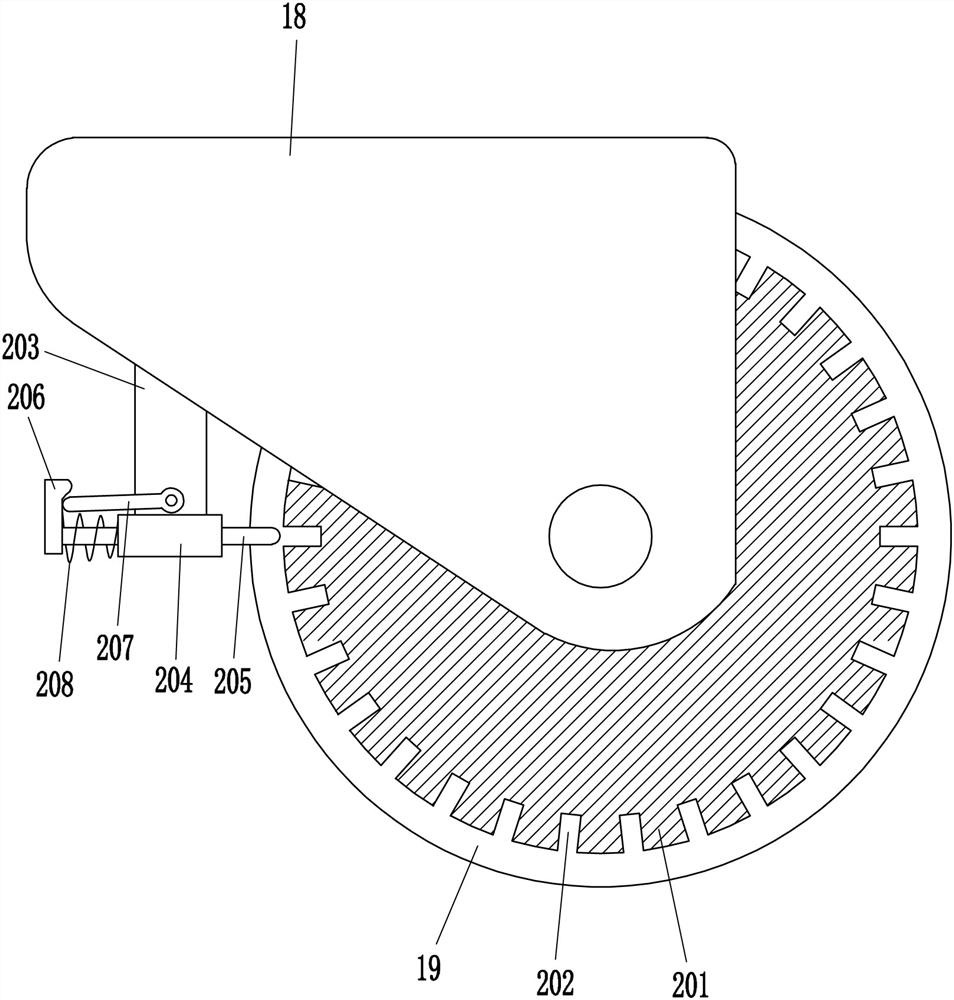
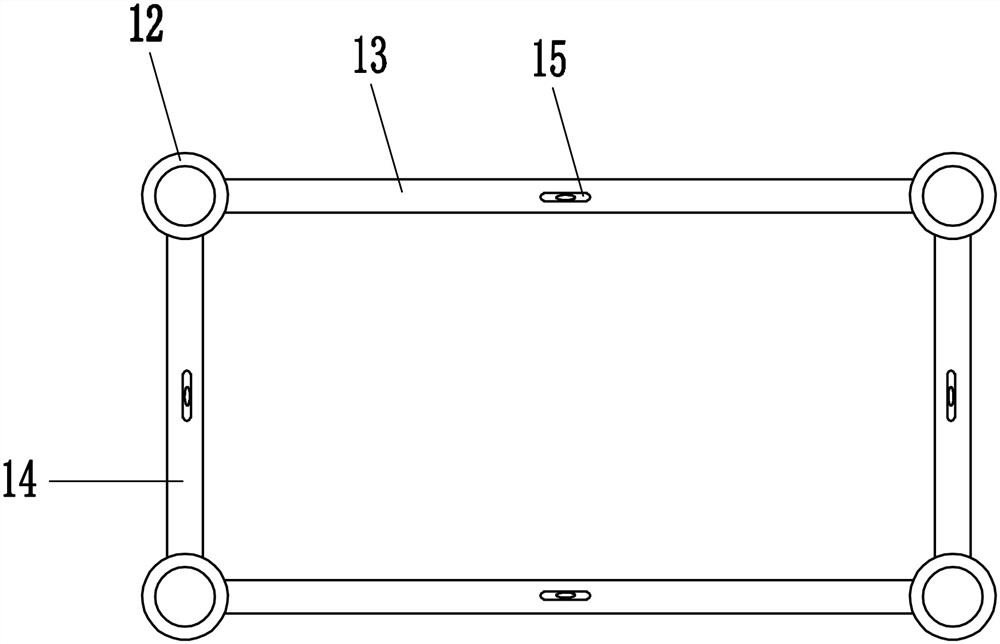
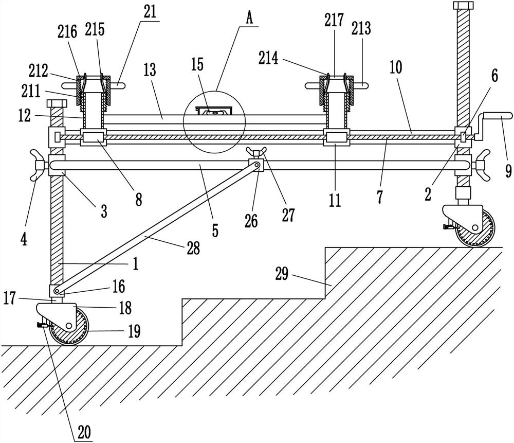
[0022] A scaffold base convenient for corridor construction for buildings, such as Figure 1-4 As shown, it includes a screw 1, a first nut 2, a first guide sleeve 3, a first disc bolt 4, a cross bar 5, a bearing seat 6, a screw 7, a second nut 8, a rocker 9, a sliding rod 10, a sliding sleeve 11, a hollow sleeve 12, a first connecting rod 13, a second connecting rod 14, a horizontal bubble 15, a first shaft sleeve 16, a first rotating shaft 17 and a mounting seat 18. The first nut 2 is located above the first guide sleeve 3, the first disc bolts 4 are arranged outside the first guide sleeves 3 on the left and right sides, the front sides of two first guide sleeves 3 on the front side are connected with cross bars 5, and the rear sides of two first guide sleeves 3 on the rear side are also connected with cross bars 5. The front sides of the two first nuts 2 on the front side are all provided with bearing seats 6, and a screw rod 7 is connected between the two bearing seats 6, two s...
Embodiment 2
[0024] A scaffold base convenient for corridor construction for buildings, such as Figure 1-4 As shown, it includes a screw 1, a first nut 2, a first guide sleeve 3, a first disc bolt 4, a cross bar 5, a bearing seat 6, a screw 7, a second nut 8, a rocker 9, a sliding rod 10, a sliding sleeve 11, a hollow sleeve 12, a first connecting rod 13, a second connecting rod 14, a horizontal bubble 15, a first shaft sleeve 16, a first rotating shaft 17 and a mounting seat 18. The first nut 2 is located above the first guide sleeve 3, the first disc bolts 4 are arranged outside the first guide sleeves 3 on the left and right sides, the front sides of two first guide sleeves 3 on the front side are connected with cross bars 5, and the rear sides of two first guide sleeves 3 on the rear side are also connected with cross bars 5. The front sides of the two first nuts 2 on the front side are all provided with bearing seats 6, and a screw rod 7 is connected between the two bearing seats 6, two s...
Embodiment 3
[0027] A scaffold base convenient for corridor construction for buildings, such as Figure 1-4 As shown, it includes a screw 1, a first nut 2, a first guide sleeve 3, a first disc bolt 4, a cross bar 5, a bearing seat 6, a screw 7, a second nut 8, a rocker 9, a sliding rod 10, a sliding sleeve 11, a hollow sleeve 12, a first connecting rod 13, a second connecting rod 14, a horizontal bubble 15, a first shaft sleeve 16, a first rotating shaft 17 and a mounting seat 18. The first nut 2 is located above the first guide sleeve 3, the first disc bolts 4 are arranged outside the first guide sleeves 3 on the left and right sides, the front sides of two first guide sleeves 3 on the front side are connected with cross bars 5, and the rear sides of two first guide sleeves 3 on the rear side are also connected with cross bars 5. The front sides of the two first nuts 2 on the front side are all provided with bearing seats 6, and a screw rod 7 is connected between the two bearing seats 6, two s...
PUM
 Abstract
Description
Claims
Application Information