Building prefabricated wall and production technology

A prefabricated assembly and production process technology, applied in construction, manufacturing tools, building types, etc., can solve problems such as inability to recycle, cannot meet shading at the same time, cumbersome on-site workload, etc., to achieve uncomplicated production process and combination The structure is simple and reliable, and the effect of improving the installation speed and construction progress

Inactive Publication Date: 2019-01-18
GUANGDONG BOZHILIN ROBOT CO LTD
View PDF6 Cites 4 Cited by
  • Summary
  • Abstract
  • Description
  • Claims
  • Application Information

AI Technical Summary

Problems solved by technology

[0002] In architecture, a fence refers to a heavy vertical space partition structure, which is used to enclose, divide or protect a certain area. Generally, it surrounds the wall of the building, and the prefabricated wall is mostly made of concrete prefabricated wall panels. As the main body, in the construction process, the earthwork is still excavated on the ground first, and then the concrete is built to form the foundation column and the column, and then bricks are used between the columns to form the wall and the top, and finally the wall is coated with cement mortar to form a whole. However, most of the existing building prefabricated fences are not safe enough for on-site construction, the on-site workload is cumbersome and wasteful, and the dust pollution and noise pollution are also relatively serious. In addition, most of the existing prefabricated fences are permanent buildings. There are also some simple fences that can play individual roles, but none of them can meet the requirements of shelter, protection, beauty, fast construction, low cost, no need to prepare materials and can achieve recycling.

Method used


Image

  • Building prefabricated wall and production technology
  • Building prefabricated wall and production technology
  • Building prefabricated wall and production technology

Examples


Embodiment Construction

[0031] In order to make the technical means, objectives, and effects of the invention easy to understand, the present invention will be further described below in conjunction with specific embodiments.

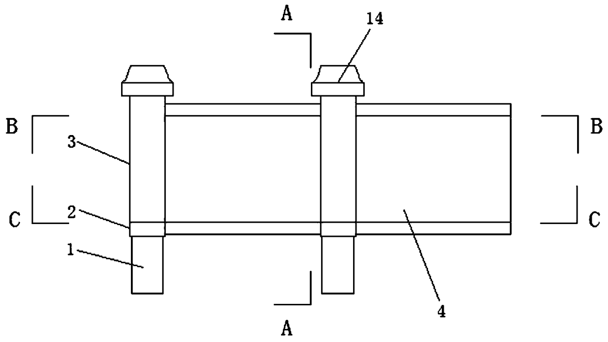
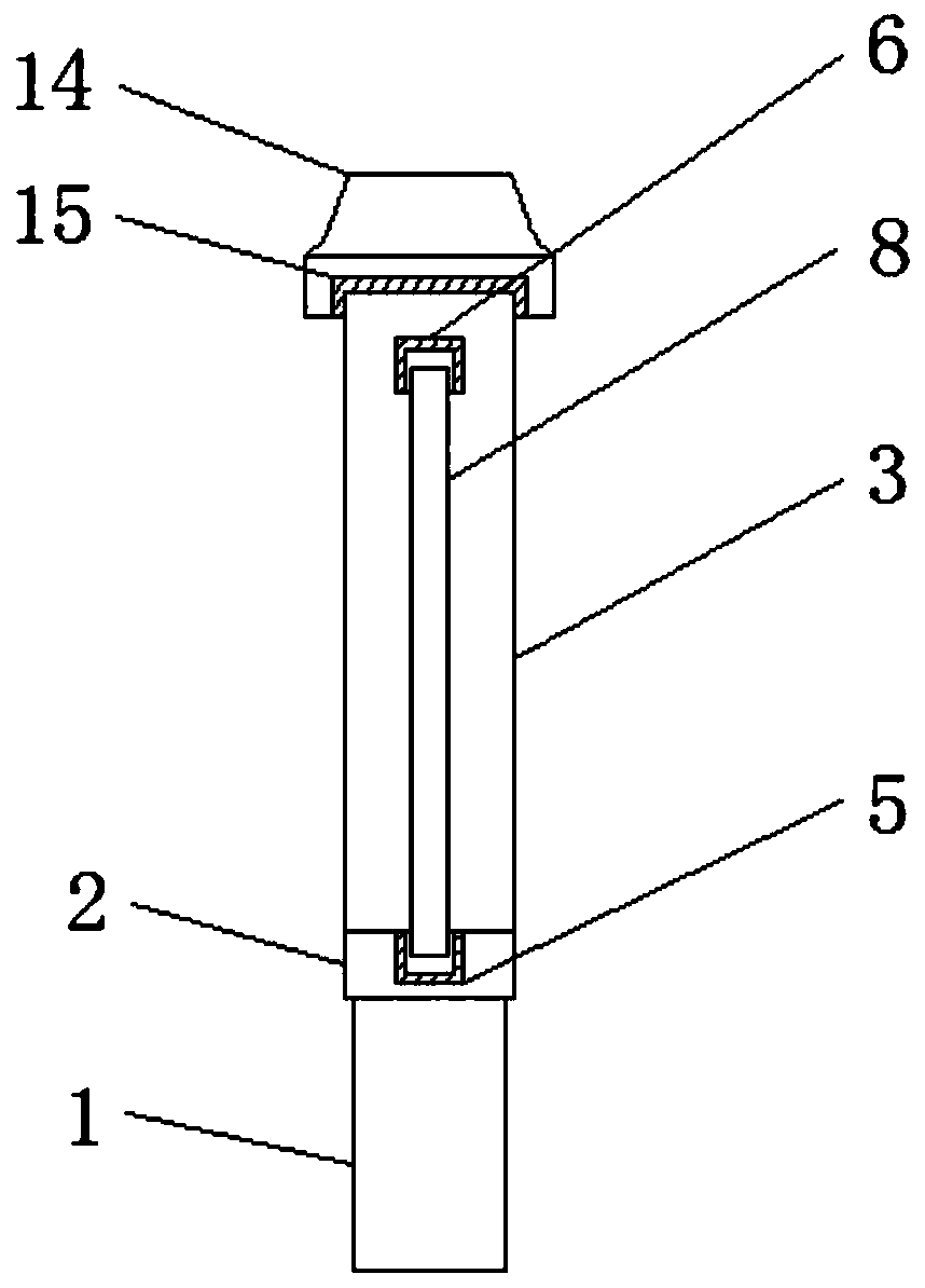
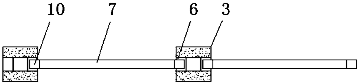
[0032] A building prefabricated enclosure, including a base column 1 and a connecting plate 2 arranged on the top of the base column 1, above the connecting plate 2 is provided with a wind-resistant column 3 through fixing bolts, adjacent to the wind-resistant column 3 A combined wall 4 is arranged between them, positioning vertical grooves 5 are arranged above both sides of the connecting plate 2, and insertion vertical grooves 6 are arranged above both sides of the wind-resistant column 3, and the combined wall 4 includes a positioning Upper plate 7, wall plate 8 and positioning lower plate 9, adjacent to the vertical slot 6 is provided with a positioning upper plate 7, the bottom of the positioning upper plate 7 is provided with a wall plate 8, the wall plate 8 The position...


PUM


Abstract

The invention provides a building prefabricated wall and a production technology thereof. The building prefabricated wall comprises a base column and a connecting plate arranged at the top of the basecolumn. Wind resistance columns are arranged above the connecting plate through fixing bolts. A combination wall is arranged between the adjacent wind resistance columns, positioning vertical groovesare formed above the two sides of the connecting plate, pluggable vertical grooves are formed above the two sides of the wind resistance columns, the combination wall comprises a positioning upper plate, a wall plate and a positioning lower plate, the positioning upper plate is arranged inside the adjacent positioning vertical grooves, the wall plate is arranged slow the positioning upper plate,the positioning lower plate is arranged below the wall plate, and the two end faces on the positioning upper plate are provided with pluggable blocks. Due to the base column, the connecting plate, thewind resistance columns and the combination wall, the fabricated structure is adopted, construction is convenient, compared with on-site construction, the wall is safer, prefabricated components of the building prefabricated wall are assembled and molded on site, real-time complete disassembling can be achieved, and after disassembling, secondary recycling can be achieved.

Description

technical field [0001] The invention relates to the field of building technology, in particular to a building prefabricated enclosure wall and a production process thereof. Background technique [0002] In architecture, a fence refers to a heavy vertical space partition structure, which is used to enclose, divide or protect a certain area. Generally, it surrounds the wall of the building, and the prefabricated wall is mostly made of concrete prefabricated wall panels. As the main body, in the construction process, the earthwork is still excavated on the ground first, and then the concrete is built to form the foundation column and the column, and then bricks are used between the columns to form the wall and the top, and finally the cement mortar is applied on the wall to form a whole. However, most of the existing building prefabricated fences are not safe enough for on-site construction, and the on-site workload is cumbersome and wasteful. Dust pollution and noise pollution...

Claims


Application Information

Patent Timeline
Patent Type & Authority Applications(China)
IPC IPC(8): E04H17/16E04H17/20B28B23/02B28B1/04B28B1/093
CPCB28B1/045B28B1/093B28B23/02E04H17/168E04H17/20
Inventor 杨泓斌张亮亮王云燕黄万禧刘博
Owner GUANGDONG BOZHILIN ROBOT CO LTD
Why Eureka
Try Eureka