Mechanism used for maintaining pressure of L-shaped part

A technology of parts and translation mechanism, which is applied in the field of mechanisms for maintaining pressure on L-shaped parts, can solve problems such as parts dislocation, and achieve the effect of avoiding dislocation and improving quality.

Pending Publication Date: 2019-01-18
SUZHOU RS TECH
View PDF29 Cites 1 Cited by
  • Summary
  • Abstract
  • Description
  • Claims
  • Application Information

AI Technical Summary

Problems solved by technology

[0005] Therefore, the technical problem to be solved by the present invention is to overcome the defect that the mechanism for maintaining pressure on L-shaped parts in the prior art is likely to cause part misalignment during the action process, and to provide a device that can avoid causing part misalignment. Mechanism for keeping pressure on L-shaped parts

Method used


Image

  • Mechanism used for maintaining pressure of L-shaped part
  • Mechanism used for maintaining pressure of L-shaped part
  • Mechanism used for maintaining pressure of L-shaped part

Examples


Embodiment 1

[0046] Such as Figure 1 to Figure 6 As shown, it is embodiment 1 provided by the present invention, and this embodiment provides a pressure maintaining device for maintaining pressure on two L-shaped parts.

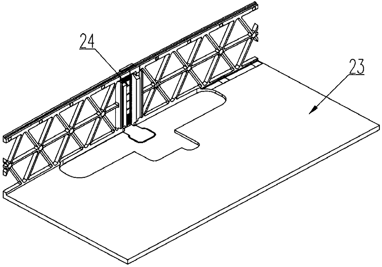
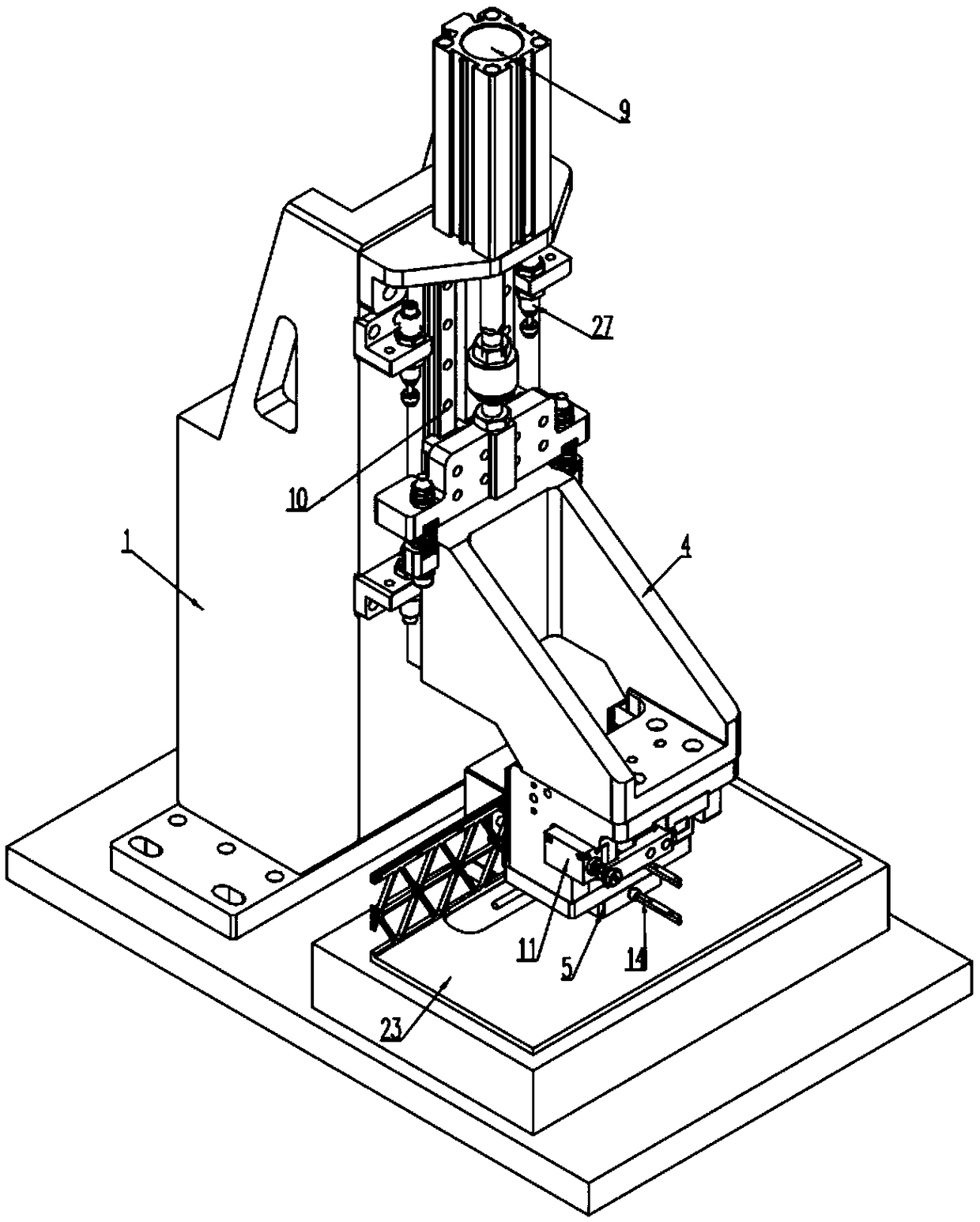
[0047] This embodiment includes a seat body 1, a positioning member 2, a first frame body 4, a first pressing member 5 and a second pressing member 6, the positioning member 2 is installed on the seat body 1, and has an L-shaped positioning surface. The L-shaped positioning surface 3 is suitable for positioning the outside of the L-shaped part; the first frame body 4 is vertically arranged on the seat body 1, and is suitable for moving up and down driven by the lifting mechanism; the first pressing part 5 It is arranged at the lower end of the first frame body 4 and is suitable for moving up and down under the drive of the first frame body 4. The first pressing member 5 is suitable for moving the L-shaped parts vertically to the lower end. The horizontal section is pres...

Embodiment approach

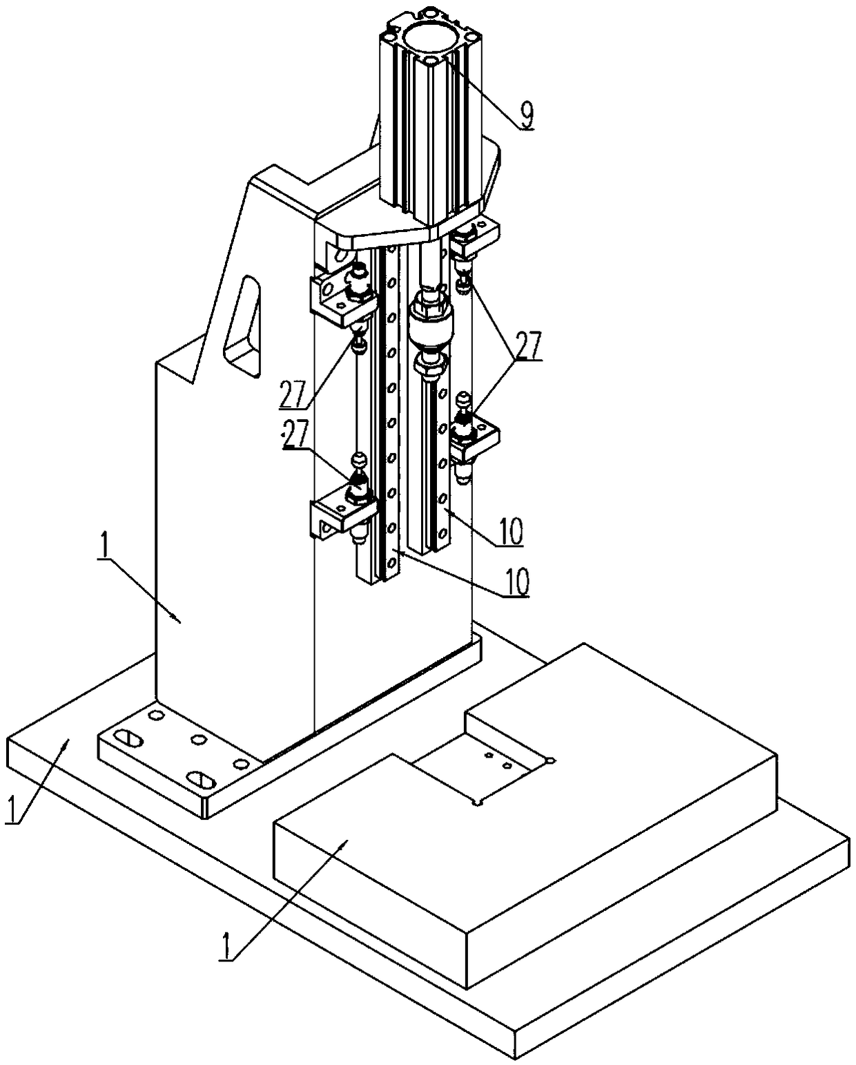
[0051] As a specific implementation of the lifting mechanism, the lifting mechanism includes a first power element 9 and a first slide rail 10, the first power element 9 is fixedly installed on the base body 1; the first slide rail 10 is vertically installed on the base body 1 Above; the first frame body 4 is slidably installed on the first slide rail 10 and is suitable for vertical movement along the first slide rail 10 driven by the power element. In this embodiment, the first power element 9 is specifically a telescopic cylinder.

specific Embodiment approach

[0052] As a specific implementation of the translation mechanism, the translation mechanism includes a second power element 11 and a second slide rail 12, the second power element 11 is fixedly installed on the first frame body 4; the second slide rail 12 is horizontally installed on On the first frame body 4; in this embodiment, the second power element 11 is specifically a telescopic cylinder. The second pressing member 6 is slidably installed on the second slide rail 12 and is suitable for sliding along the second slide rail 12 driven by the second power element 11 .

[0053] As a more optimal embodiment of this equipment, between the first frame body 4 and the seat body 1, between the first power element 9 and the first pressing part 5, between the second pressing part Buffer components are installed between 6 and the second power element 11. By installing a buffer member between the above structures, on the one hand, it can provide pressure for components that require pr...


PUM


Abstract

The invention provides a mechanism used for maintaining pressure of an L-shaped part, and belongs to the technical field of pressure maintaining. The mechanism comprises a base, a positioning part, afirst frame, a first pressing fit part, a second pressing fit part and a second frame. When the mechanism is used for maintaining the pressure of the L-shaped part, part dislocation can be effectivelyavoided, the quality of the whole product is kept, and meanwhile the mechanism has the advantage that commissioning is convenient.

Description

technical field [0001] The invention relates to the technical field of pressure maintaining equipment, in particular to a mechanism for maintaining pressure on L-shaped parts. Background technique [0002] With the continuous upgrading of electronic products and optical products, the volume of products is getting smaller and smaller, and the structural integration is getting higher and higher. In order to improve the structural integrity of the product and reduce the volume of the product, some components are often embedded on the product shell, such as the product LOGO, indicator lamp housing, product yin and yang lines, etc. To embed LOGO, indicator lights and other components at the corners, it is necessary to design the LOGO, indicator lights and other parts into an L-shape, and then install these L-shaped LOGO, indicator lights and other parts to the shell by dispensing, pressure-holding and other processes. at the corner. In this application, we collectively refer to...

Claims


Application Information

Patent Timeline
Patent Type & Authority Applications(China)
IPC IPC(8): F16B11/00
CPCF16B11/006
Inventor 吴加富缪磊许新星冯小平
Owner SUZHOU RS TECH
Why Eureka
Try Eureka