Eureka AIR delivers breakthrough ideas for toughest innovation challenges, trusted by R&D personnel around the world.

Vibration arm connecting structure

A connection structure, vibrating arm technology, applied in non-rotational vibration suppression, threaded fasteners, screws, etc., can solve the problems of loosening, misalignment and wear, large noise and temperature rise, and deterioration of connection conditions, and achieve a degree of contact sticking. The effect of increasing the wear resistance and reducing the degree of wear

Pending Publication Date: 2019-01-18
CHINA TOBACCO HENAN IND
View PDF0 Cites 1 Cited by
  • Summary
  • Abstract
  • Description
  • Claims
  • Application Information

AI Technical Summary

Problems solved by technology

The vibrating arm and the transmission support are fixedly connected by fixed pins and rubber buffer sleeves. During use, the mating surfaces of the fixed pins and rubber buffer sleeves are prone to loosening, misalignment and wear due to impact and friction damage. The connection condition deteriorates, the gap is too large and it is not easy to compensate, and the transmission parts are frequently damaged, and the noise and temperature rise are large.

Method used


Image

  • Vibration arm connecting structure

Examples


Embodiment Construction

[0011] The present invention is further described below in conjunction with the accompanying drawings.

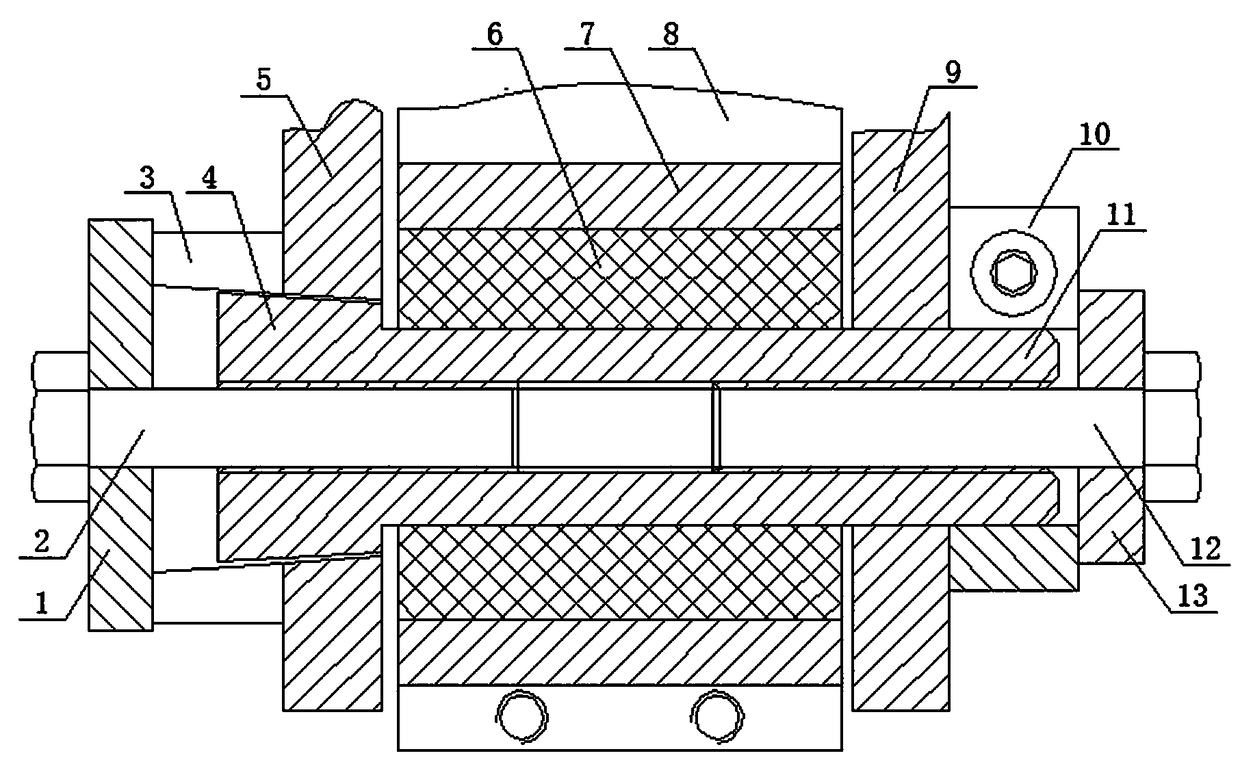
[0012] like figure 1 As shown, the present invention includes a vibrating arm 8 and a transmission support, the transmission support includes a left connecting ear 5 and a right connecting ear 9, and a trumpet-shaped through hole is provided on the left connecting ear 5. The inner diameter gradually decreases from left to right, the right connecting ear 9 is provided with a straight through hole coaxially arranged with the horn-shaped through hole, and between the left connecting ear 5 and the right connecting ear 9, there is a through-horn-shaped through hole and a straight through hole. The connection pin of the hole, the left end of the connection pin is the flared end 4, and the connection pin of the right part of the flared end 4 is the cylindrical shaft 11, and the diameter of the cylindrical shaft 11 is not larger than the flared end The outer diameter of the flared...


PUM


Abstract

The invention discloses a vibration arm connecting structure used for vibrating equipment. The vibration arm connecting structure comprises a vibrating arm and a drive support, the drive support comprises a left connecting lug and a right connecting lug, a horn-shaped through hole is formed in the left connecting lug, a straight-through hole is formed in the right connecting lug, a connecting pinshaft which penetrates through the horn-shaped through hole and the straight-through hole is assembled between the left connecting lug and the right connecting lug, the left end of the connecting pinshaft is a horn-shaped end, a right inner thread hole is formed in the right end of the connecting pin shaft, a flat sleeve is connected to the right side wall of the right connecting lug, a tension bolt is in threaded connection inside the right inner thread hole, and a right end cover is slidingly connected to the tension bolt. One end of the vibrating arm is located between the left connectinglug and the right connecting lug and connected with the connecting pin shaft; one end of the connecting shaft is designed into a horn-shaped end, the other end of the connecting pin shaft is designedinto a cylindrical shaft in a structural form, in this way, a locking component for the horn-shaped end is omitted, and it is avoided that an original locking component is easy to deform.

Description

technical field [0001] The invention belongs to the technical field of vibration equipment manufacturing, and particularly relates to a vibration arm connection structure for vibration equipment. Background technique [0002] Vibration tank type vibration equipment is widely used in industrial production, and its transmission structure generally uses an eccentric body to drive the vibrating arm to reciprocate, so that the transmission support connected to the vibrating arm generates front and rear vibration movement. The vibrating arm and the transmission support are fixedly connected by a fixed pin and a rubber buffer sleeve. During use, the fixed pin and the mating surface of the rubber buffer sleeve are easily loosened, dislocated and worn due to impact and friction damage. The connection condition is deteriorated, the gap is too large and it is difficult to compensate, and the transmission parts are frequently damaged, noise and temperature rise are large and other fault...

Claims


Application Information

Patent Timeline
Patent Type & Authority Applications(China)
IPC IPC(8): F16B19/02F16F15/08
CPCF16B19/002F16B19/02F16F15/08F16B2019/006
Inventor 米存军赵文龙柴超李秀芳石军赵健
Owner CHINA TOBACCO HENAN IND
Why Eureka
Eureka Blog
Learn More