Building plate material surface smoothness detection device

A technology for surface flatness and building boards, applied in the direction of mechanical roughness/irregularity measurement, etc., can solve the problems of inconvenient board flatness, drawing boards placed together, etc., to achieve intuitive detection results, high detection accuracy, and operability good sex effect

Active Publication Date: 2019-01-18
宁夏宏源建科检测有限公司
View PDF10 Cites 9 Cited by
  • Summary
  • Abstract
  • Description
  • Claims
  • Application Information

AI Technical Summary

Problems solved by technology

However, the boards tested by this utility model can not be placed together with the drawing boards corresponding to the...

Method used


Image

  • Building plate material surface smoothness detection device
  • Building plate material surface smoothness detection device
  • Building plate material surface smoothness detection device

Examples


specific Embodiment approach 1

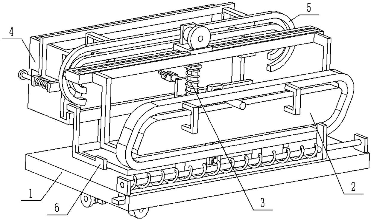
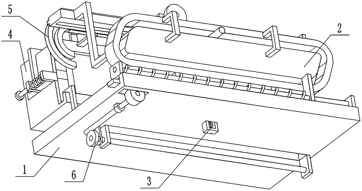
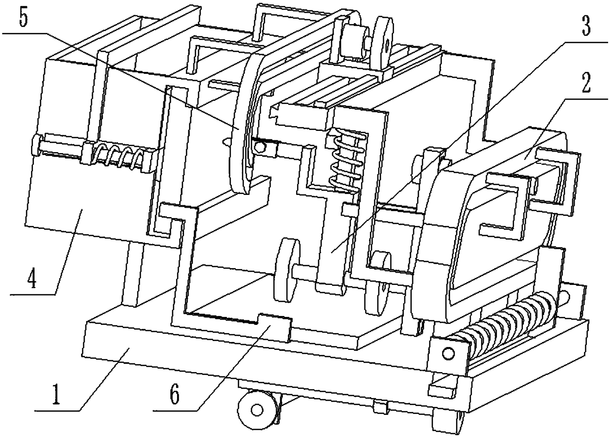
[0038] Combine below Figure 1-13 Describe this embodiment, a device for detecting the surface roughness of building boards, including a detection platform 1, a slide rail 2, a reciprocating slide seat 3, a drawing board storage seat 4, a guide rail 5, and a reciprocating dial 6. The detection platform 1 is There are dial chute 1-1, through groove 1-2, rack groove 1-3 and gear groove 1-4; Located between the dial chute 1-1 and the rack groove 1-3, the gear groove 1-4 communicates with the rack groove 1-3;

[0039] The slide rail 2 includes a support seat 2-1, a chute frame 2-2, a U-shaped seat 2-3, a center plate 2-4, a folding rod 2-5, a horizontal sliding frame 2-6, and a rack I 2- 7. The trapezoidal convex strip 2-8 and the closed chute 2-9; the chute frame 2-2 is fixedly connected to the detection platform 1 through two support seats 2-1, and the center plate 2-4 passes through two U-shaped seats 2 -3 is fixedly connected to the center of the chute frame 2-2, a closed ch...

specific Embodiment approach 2

[0044] Combine below Figure 1-13 To illustrate this embodiment, the reciprocating slide 3 also includes a motor 3-5 and a drive wheel 3-6; the lower end of the drive wheel 3-6 passes through the slot 3-4 and is engaged with the rack I 2-7 to drive Wheel 3-6 is fixedly connected on the output shaft of motor 3-5, and motor 3-5 is fixedly connected on the L-shaped sliding seat 3-1 by motor seat. The motor 3-5 is a forward and reverse motor. Connect the motor 3-5 to the power supply and the control switch through the wire and turn it on. The motor 3-5 drives the driving wheel 3-6 to rotate, and the driving wheel 3-6 meshes with the rack Ⅰ 2-7 Drive the L-shaped sliding seat 3-1 to move left and right on the horizontal sliding frame 2-6.

specific Embodiment approach 3

[0045] Combine below Figure 1-13 To illustrate this embodiment, the drawing board receiving seat 4 also includes a first convex plate 4-4, a second convex plate 4-5, a spring sleeve rod 4-6, an extrusion plate chute 4-7, an extrusion plate 4-8, tension spring 4-9, door-shaped plate 4-10 and support plate 4-11; the storage seat body 4-1 is fixedly connected to the detection platform 1 through the support plate 4-11, and the storage seat body 4-1 The two ends of 1 are respectively fixedly connected with a first convex plate 4-4 and a second convex plate 4-5, and the first convex plate 4-4 and the second convex plate 4-5 are fixedly connected with a spring sleeve rod 4-6 Both ends of the storage seat body 4-1 are provided with an extrusion plate chute 4-7 communicating with the interior of the storage seat body 4-1, and the extrusion plate 4-8 is slidably connected to the interior of the storage seat body 4-1. The two ends of the extruding plate 4-8 are respectively slidably co...


PUM


Abstract

The invention relates to the field of building material detection technology, and more particularly to a building plate material surface smoothness detection device. A plectrum plate chute, a throughgroove, a rack groove and a gear groove are arranged on a detection platform. The plectrum plate chute is arranged at a center position of the detection platform. The through groove is located betweenthe plectrum plate chute and the rack groove. The gear groove is in communication with the rack groove. A chute frame is fixedly connected to the detection platform through two support seats. The device can judge balance degrees of plate materials through shapes of straight lines drawn on drawing plates by a drawing pen, and has the advantages of good operability, intuitive detection results, high detection precision and the like; the plate materials after detection can realize automatic plate unloading, a drawing plate which corresponds to each plate material and has a drawn detection resultand the plate material can be placed together in an attaching manner, a worker is familiar with smoothness of each plate material through the drawing plate on each plate material, and thus subsequentmachining and improvement are facilitated; and the drawing plate can realize an automatic plate loading function.

Description

technical field [0001] The invention relates to the technical field of building material detection, in particular to a device for detecting the surface roughness of building boards. Background technique [0002] The existing patent number is CN201620595396.3 plate detection device, the utility model discloses a plate detection device, which includes a frame 1, a detection table 2 is arranged on the frame 1, and the plate 3 to be detected is placed on the On the detection platform 2; a detection trolley is provided on the plate 3, and the trolley is connected with a balance bar 7, and a drawing pen 9 is provided at one end of the balance bar 7; an adjustable column 4 is provided on one side of the frame 1 , the adjustable column 4 is provided with a drawing board 10 facing the drawing pen 9; hinged. The utility model judges the balance degree of the board through the shape of the straight line drawn by the drawing pen at the end of the balance bar on the upper part of the b...

Claims


Application Information

Patent Timeline
IPC IPC(8): G01B5/28
CPCG01B5/28
Inventor 卢宣羽
Owner 宁夏宏源建科检测有限公司
Why Eureka
Try Eureka