Broken line repairing method

A repair method and a technology for repairing wires, which are applied in nonlinear optics, optics, instruments, etc., can solve problems such as easy generation of parasitic capacitance, poor electrical signals of wires and adjacent wires, signal attenuation of adjacent wires, etc.

Inactive Publication Date: 2019-01-18
TCL CHINA STAR OPTOELECTRONICS TECH CO LTD
View PDF5 Cites 6 Cited by
  • Summary
  • Abstract
  • Description
  • Claims
  • Application Information

AI Technical Summary

Problems solved by technology

[0004] (1) The repair line of the wire is in electrical contact with the transparent conductive layer corresponding to the wire, and the transparent conductive layer corresponding to the wire 14 forms a short circuit (short) with the transparent conductive layer corresponding to the adjacent wire, due to the influence of the potential change of the transparent conductive layer , resulting in poor electrical signals carried by the conductor and adjacent conductors
[0005] (2) When the polarities of the electrical signals (such as data signals) carried by two adjacent wires are opposite, because the repair wire is in electrical contact with the transparent conductive layer corresponding to the adjacent wire, the The electrical signal polarity of the transparent conductive layer is the same, and the electrical signal polarity of the adjacent wire is opposite to that of the corresponding transparent conductive layer, so parasitic capacitance is easily generated between the two, causing signal attenuation of adjacent wires

Method used


Image

  • Broken line repairing method
  • Broken line repairing method
  • Broken line repairing method

Examples


Embodiment Construction

[0029] In order to make the purpose, technical solution and effect of the present application more clear and definite, the present application will be further described in detail below with reference to the accompanying drawings and examples. It should be understood that the specific embodiments described here are only used to explain the present application, and the word "embodiment" used in the description of the present application is intended to be used as an example, illustration or illustration, and is not intended to limit the present application.

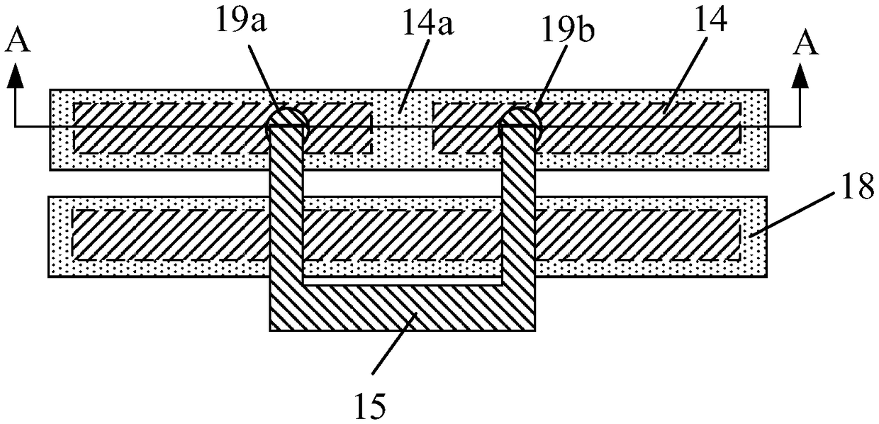
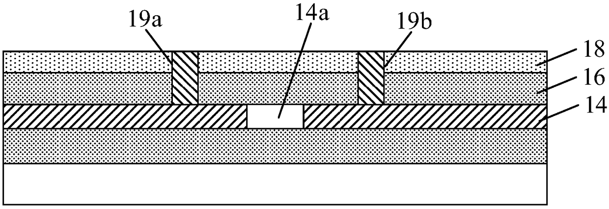
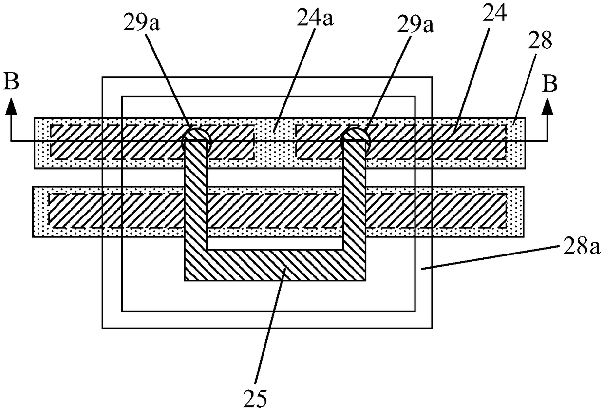
[0030] see Figure 5 , the application provides a disconnection repair method, comprising the following steps:

[0031] Step S1, please refer to image 3 and Figure 4 , providing an array substrate 20, the array substrate 20 has broken wires 24 in the signal fanout area (fanoutarea), the wires 24 are covered with a first insulating layer 26, and the first insulating layer 26 is covered with a transparent conductive layer ...


PUM


Abstract

The invention provides a broken line repairing method. The broken line repairing method comprises the following steps of providing an array substrate, wherein a broken line is in a signal fan-out areaof the array substrate, and a first insulating layer and a transparent conductive layer cover the line; respectively arranging a first via hole and a second via hole at two ends of a broken part of the line; forming a repairing line, and connecting two ends of the broken part of the line through the first via hole and the second via hole; and forming a closed annular opening on the transparent conductive layer, wherein the repairing line is in an area enclosed by the closed annular opening. A part of the repairing line, electrically contacted with the transparent conductive layer corresponding to an adjacent line, is limited in the closed annular opening only, so that the impact on an electrical signal carried by the adjacent line is reduced.

Description

technical field [0001] The present application relates to a display technology, in particular to a disconnection repair method. Background technique [0002] The manufacturing process of a liquid crystal display panel generally includes an array process, a cell process (lamination of a thin film transistor substrate and a color filter substrate) and a module assembly process. Disconnection defects often occur during the array manufacturing process. For the disconnection defects on the signal fan-out area where the scan lines and data lines extend to the non-display area, the existing technology usually uses the discontinuity repair technology on the display area to repair the signal. A wire break defect on a fan-out area. [0003] Such as figure 1 with figure 2 As shown, the existing disconnection repair method is: on the insulating layer 16 and the transparent conductive layer 18 at the two ends of the wire 14 breakage 14a, respectively set up two via holes 19a and 19b,...

Claims


Application Information

Patent Timeline
Patent Type & Authority Applications(China)
IPC IPC(8): G02F1/1362H01L21/77H01L27/12
CPCG02F1/136227G02F1/136259G02F1/136286H01L27/124H01L27/1259
Inventor 周德利
Owner TCL CHINA STAR OPTOELECTRONICS TECH CO LTD
Why Eureka
Try Eureka