A pin needle structure and an electronic device including the pin needle structure

A technology of electronic equipment and boss structure, which is applied to circuits, electrical components, parts of connecting devices, etc., can solve problems such as poor contact, rusting of pin needles, and damage to plastic shells, so as to improve productivity and reduce The effect of the number of repairs

Inactive Publication Date: 2019-01-18
GOERTEK INC
View PDF10 Cites 1 Cited by
  • Summary
  • Abstract
  • Description
  • Claims
  • Application Information

AI Technical Summary

Problems solved by technology

However, due to the small size of the pin needle, it is easy to cause damage to the pin needle and the plastic shell of the device during injection molding, and there is a gap between the pin needle and the plastic shell, which will easily cause water to enter the plastic shell, and the pin needle will rust when it enters the water.
And when the contact surface of the pin pin with the external device circuit or the internal circuit of the device is wrapped by plastic residue, it is easy to have poor contact during electrical connection.

Method used


Image

  • A pin needle structure and an electronic device including the pin needle structure
  • A pin needle structure and an electronic device including the pin needle structure
  • A pin needle structure and an electronic device including the pin needle structure

Examples


Embodiment Construction

[0034] In order to illustrate the present invention more clearly, the present invention will be further described below in conjunction with preferred embodiments and accompanying drawings. Similar parts in the figures are denoted by the same reference numerals. Those skilled in the art should understand that the content specifically described below is illustrative rather than restrictive, and should not limit the protection scope of the present invention.

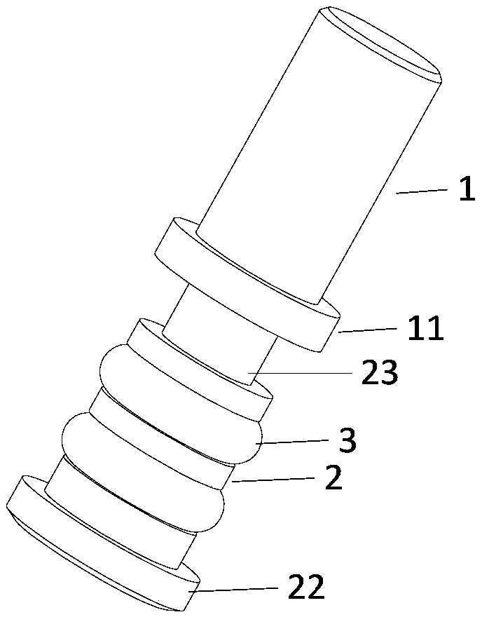
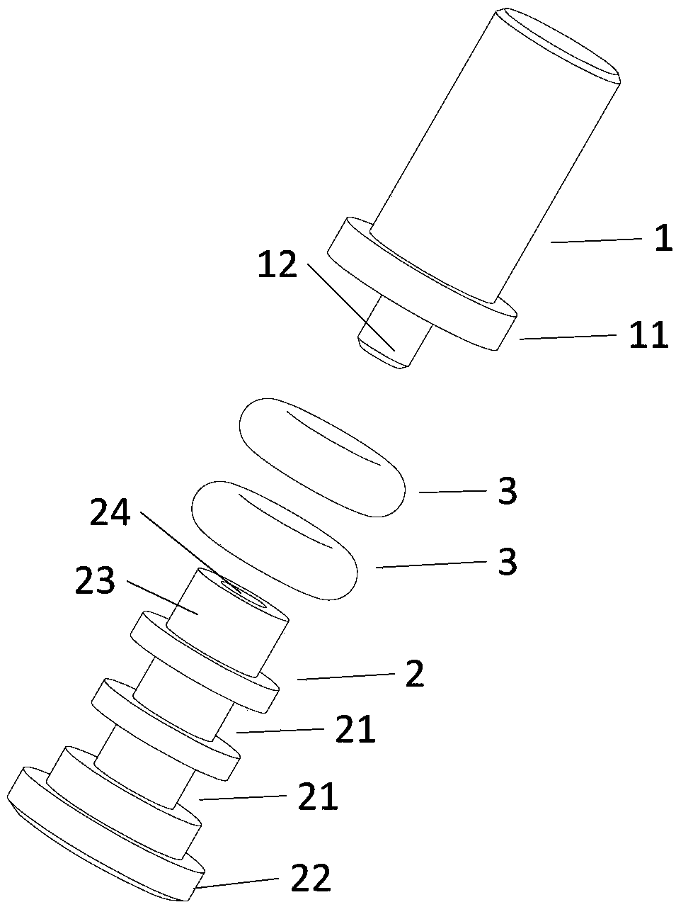
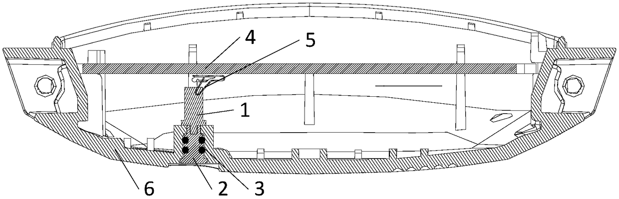
[0035] In the prior art, the pin needle is usually combined with plastic through an in-mold injection molding process, but it is easy to cause damage to the pin needle and the plastic shell of the device during injection molding. The invention provides a two-stage pin needle structure and electronic equipment including the pin needle structure, which can avoid damage to the pin needle and the plastic casing of the equipment during in-mold injection molding.

[0036] Specifically, a detailed description will be given below ...


PUM


Abstract

The invention discloses a pin needle structure and an electronic device comprising the pin needle structure. The pin needle comprises a first body part located at an upper position and a second body part located at a lower position. An end portion of the first body portion remote from the second body portion and for forming an electrical connection with an internal conductive member of the electronic device; An end portion of the first body portion adjacent to the second body portion and an end portion of the second body portion adjacent to the first body portion are combined and fixed to forman electrical connection; An end portion of the second body portion remote from the first body portion is used for forming an electrical connection with an external circuit. The two-stage pin pin structure and the electronic device including the pin pin structure can avoid damage to the pin pin and the device plastic housing during in-mold injection molding.

Description

technical field [0001] The invention relates to the technical field of electronic equipment. More specifically, it relates to a pin needle structure and electronic equipment including the pin needle structure. Background technique [0002] In the prior art, the pin needle is usually combined with plastic through an in-mold injection molding process to achieve a waterproof effect of 50 meters. However, due to the small size of the pin needle, it is easy to cause damage to the pin needle and the plastic housing of the device during injection molding, and a gap is formed between the pin needle and the plastic housing, which may easily cause water to enter the plastic housing and cause the pin needle to rust. And when the contact surface of the pin needle with the external device circuit or the device internal circuit is wrapped by plastic residue, it is easy to have poor contact during electrical connection. [0003] Therefore, it is necessary to provide a pin needle with a n...

Claims


Application Information

Patent Timeline
Patent Type & Authority Applications(China)
IPC IPC(8): H01R13/02H01R13/52H01R13/523
CPCH01R13/02H01R13/521H01R13/523
Inventor 刘洋张军国
Owner GOERTEK INC
Why Eureka
Try Eureka