
Infrared thermal imager and infrared thermal imager vibration reduction device

A technology of infrared thermal imaging camera and shock absorbing device, which is applied in image communication, television, coil spring, etc., and can solve the problems of being unable to adapt to different impact environments

Active Publication Date: 2020-10-20
IRAY TECH CO LTD
View PDF7 Cites 0 Cited by
  • Summary
  • Abstract
  • Description
  • Claims
  • Application Information

AI Technical Summary

Problems solved by technology

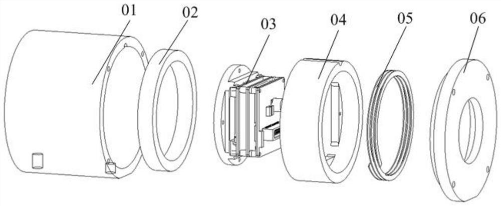
[0005] After the infrared imager is assembled, the relative position of each component in the shell is determined, and the shock absorption capacity of the shock-absorbing spring and the high-damping pad is determined, which cannot adapt to different impact environments

Method used


Image

  • Infrared thermal imager and infrared thermal imager vibration reduction device
  • Infrared thermal imager and infrared thermal imager vibration reduction device
  • Infrared thermal imager and infrared thermal imager vibration reduction device

Examples


Embodiment Construction

[0032] The following will clearly and completely describe the technical solutions in the embodiments of the present invention with reference to the accompanying drawings in the embodiments of the present invention. Obviously, the described embodiments are only some, not all, embodiments of the present invention. Based on the embodiments of the present invention, all other embodiments obtained by persons of ordinary skill in the art without making creative efforts belong to the protection scope of the present invention.

[0033] The core of the present invention is to provide a shock absorbing device for an infrared thermal imager, which can make the infrared thermal imager better adapt to different impact environments. Another core of the present invention is to provide an infrared thermal imaging camera including the shock absorbing device for the infrared thermal imaging camera, which can better adapt to different impact environments.

[0034] In a specific embodiment of the...


PUM


Abstract

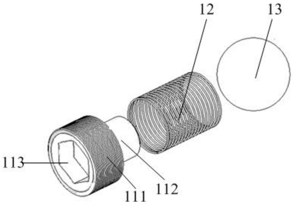
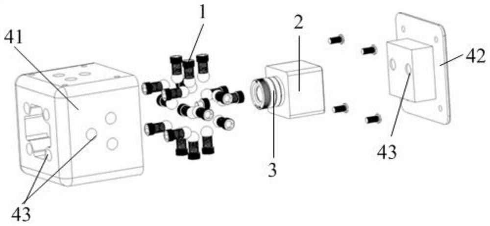
The invention discloses a shock absorbing device for an infrared thermal imager, which comprises a thermal imager casing, on which a shock absorbing assembly for shock-absorbing a core assembly in a preset direction is arranged, and the shock absorbing assembly includes a fixed Fasteners on the thermal imager housing and shock absorbing springs for correspondingly compressing between the fasteners and the movement assembly, and the fixing positions of the fasteners on the thermal imager housing are adjustable. In actual use, the core components are located in the thermal imager housing, and by adjusting the fixed position of the fasteners on the thermal imaging camera housing, it can be adjusted according to the vibration and impact magnitude that the infrared thermal imaging camera may receive in the actual use environment. Adjusting the damping value of the shock absorbing spring to the movement assembly realizes the adjustable shock absorbing capacity of the shock absorbing assembly and has a high ability to adapt to the environment. The invention also discloses an infrared thermal imager comprising the shock absorbing device of the infrared thermal imager, which can better adapt to different impact environments.

Description

technical field [0001] The invention relates to the technical field of infrared imaging equipment, in particular to an infrared thermal imager shock absorber and an infrared thermal imager. Background technique [0002] Infrared imaging is a kind of infrared radiation imaging based on the target itself. It is a passive imaging method. It is less affected by the weather such as fog and haze, and can work around the clock. It has a wide range of applications in many fields such as automobile auxiliary driving. [0003] Due to the complex use environment, vibration and shock will cause damage to the electronic components inside the infrared camera, and the final image will also be affected, resulting in a series of problems such as blurred screen and split screen. Therefore, it is very necessary to carry out shock reduction treatment on infrared thermal imaging cameras to improve the reliability of its products and imaging quality. [0004] In the prior art, see figure 1 , th...

Claims


Application Information

Patent Timeline
Patent Type & Authority Patents(China)
IPC IPC(8): H04N5/33H04N5/225F16F15/04
CPCH04N5/33F16F15/04F16F2238/026H04N23/51H04N23/54H04N23/55
Inventor 周京
Owner IRAY TECH CO LTD
Learn More