Milling cutter disc welding fixture and welding method applying same

A technology of welding tooling and cutter head, which is applied in welding equipment, laser welding equipment, manufacturing tools, etc., and can solve the problem of uncontrollable welding deformation

Inactive Publication Date: 2019-01-22
HARBIN UNIV OF SCI & TECH
View PDF5 Cites 0 Cited by
  • Summary
  • Abstract
  • Description
  • Claims
  • Application Information

AI Technical Summary

Problems solved by technology

In the present invention, a positioning and clamping device is provided in each slit on the main body of the cutterhead to complete the positioning and clamping of the slit wall during the welding process to ensure that no welding deformation o...

Method used


Image

  • Milling cutter disc welding fixture and welding method applying same
  • Milling cutter disc welding fixture and welding method applying same
  • Milling cutter disc welding fixture and welding method applying same

Examples


Embodiment Construction

[0075] The present invention will be described in detail below in conjunction with the accompanying drawings.

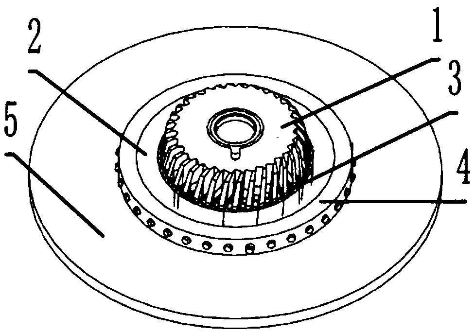
[0076] combine Figure 1-Figure 2 As shown, a milling cutter head welding tool disclosed in this embodiment includes a cutter head body 1, a cutter head outer ring 2, a base 5, a pre-tightening ring 4, and a cutter head positioning and clamping device 3; the cutter head The outer ring 2 is fixedly sleeved on the cutterhead main body 1, the preload ring 4 is connected with the cutterhead outer ring 2 through several sets of threaded connectors, and the preload ring 4 is also fixed on the base by screws 5, several sets of knife grooves are processed on the cutterhead main body 1, and a set of cutterhead positioning and clamping devices 3 are arranged in each group of cutterhead positioning and clamping devices 3, and the cutterhead positioning and clamping devices 3 are fixedly arranged on the base 5 on.

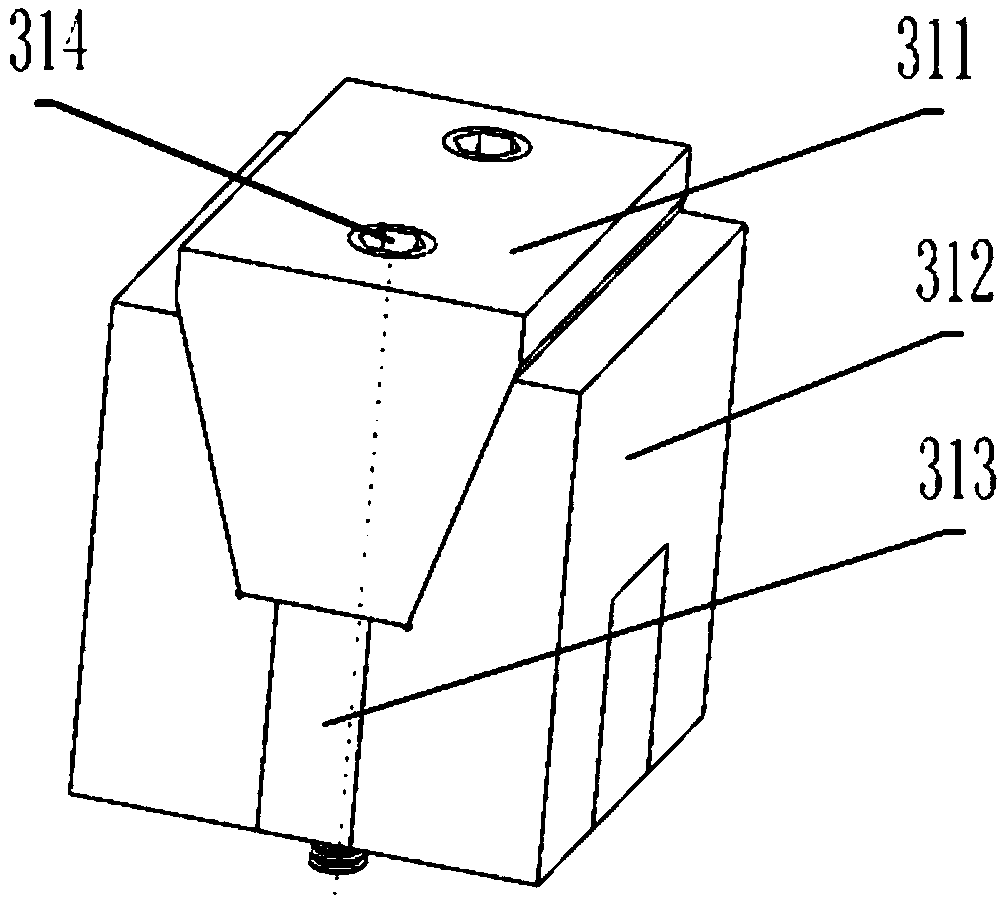
[0077] Specifically, the cutter head positioning and clamping...


PUM


Abstract

The invention relates to the technical field of milling cutter disc welding, in particular to a milling cutter disc welding fixture and a welding method applying the same and solves problems of weldment shape changing and dimensional accuracy reduction due to welding deformation in a welding process of a milling cutter disc. A cutter disc outer ring fixedly sleeves a cutter disc body, and a pre-tightening ring is connected with the cutter disc outer ring through a plurality of groups of threaded connectors and fixed to a base through a screw. The cutter disc body is provided with a plurality of groups of cutter grooves, and cutter disc positioning and clamping devices are arranged in the cutter grooves respectively and fixedly arranged on the base. By arrangement of the positioning and clamping devices in the cutter grooves of the cutter body, cutter groove wall positioning and clamping are completed in a welding process, so that welding deformation in the welding process is avoided; by adjustment of the positioning and clamping devices, control of welding deformation at any time in the welding process can be guaranteed, and the problem of uncontrollable welding deformation is solved.

Description

technical field [0001] The invention relates to the technical field of milling cutter welding, in particular to a milling cutter disc welding tool and a welding method using the tool. Background technique [0002] A milling cutter is a rotating tool with one or more teeth for milling; each tooth cuts off the allowance of the workpiece intermittently in turn during work. Milling cutters are mainly used for machining planes, steps, grooves, forming surfaces and cutting off workpieces on milling machines; [0003] During the welding process of the milling cutter head, welding deformation will definitely occur. Welding deformation changes the shape of the weldment and reduces the dimensional accuracy; in the production of welded structures, it is very important to reduce welding deformation. Although people have explored a variety of methods to reduce welding deformation, the traditional method is often performed separately after welding, resulting in high cost and low efficie...

Claims


Application Information

Patent Timeline
IPC IPC(8): B23K26/21B23K26/70
CPCB23K26/21B23K26/702
Inventor 王志刚王杰
Owner HARBIN UNIV OF SCI & TECH
Why Eureka
Try Eureka