An emergency stop assistant device and an emergency stop method

A technology of emergency braking and auxiliary devices, applied in the direction of braking transmission devices, manual starting devices, brakes, etc., can solve the problems of difficult response of hands and feet, limited braking torque, low safety, etc., to achieve increased safety and low cost , the effect of simple structure

Active Publication Date: 2019-01-22
厦工(三明)重型机器有限公司
View PDF5 Cites 2 Cited by
  • Summary
  • Abstract
  • Description
  • Claims
  • Application Information

AI Technical Summary

Problems solved by technology

[0005] However, when the speed of large-tonnage construction machinery is fast, the air-assisted hydraulic braking system does not actively participate in braking when the emergency brake button 71 is pressed, and the braking torque output by full hydraulic braking alone is limited, which ensures safety. Not high; a small number of experienced drivers can step on the air brake valve 2 to assist braking while pressing the emergency brake button 71; emergency situations are often instantaneous, and it is difficult to respond with hands and feet at the same time

Method used


Image

  • An emergency stop assistant device and an emergency stop method
  • An emergency stop assistant device and an emergency stop method

Examples


Embodiment 1

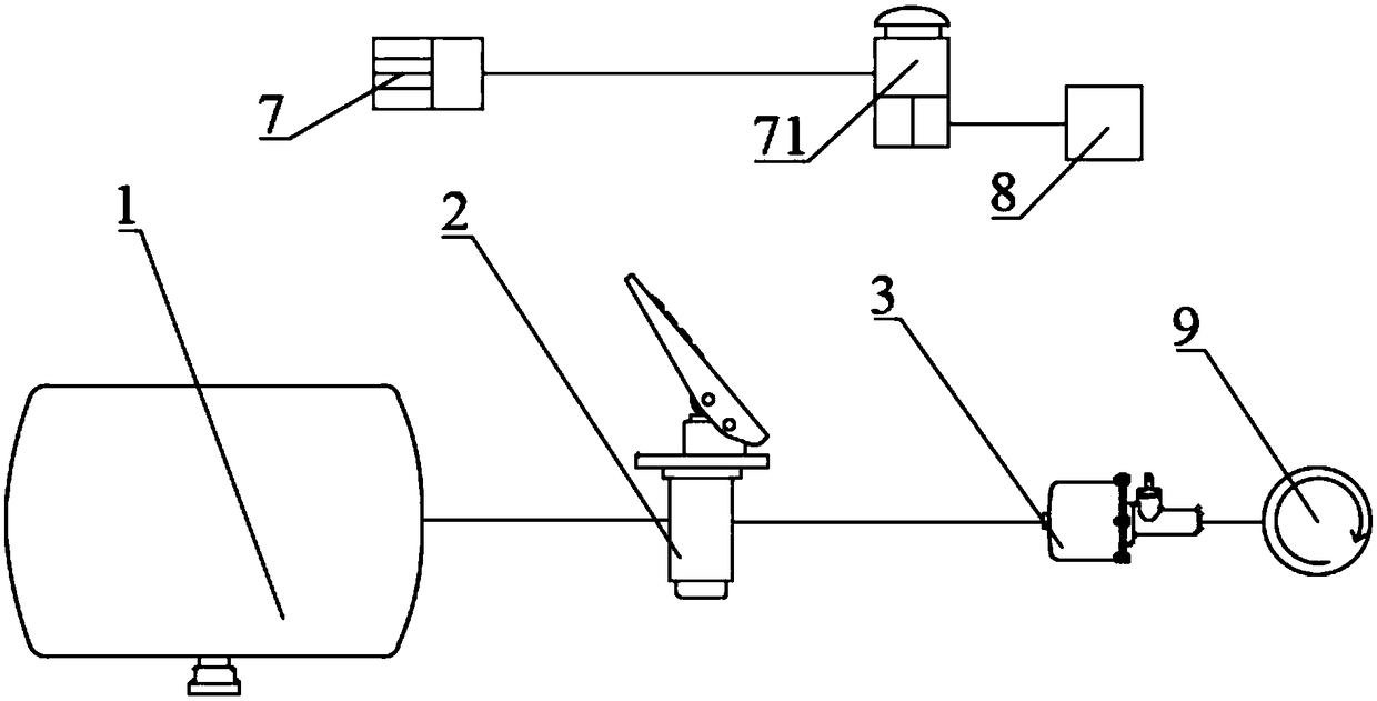
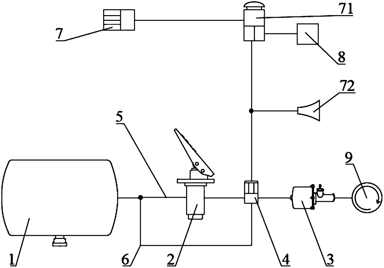
[0043] Please refer to the attached figure 2 As shown, an emergency brake auxiliary device includes an emergency brake button 71, a generator 7, an air storage tank 1, an air brake valve 2 and an air booster pump 3, and the air storage tank 1 and the air brake valve 2 connection, a pneumatic solenoid valve 4 is arranged between the air brake valve 2 and the air booster pump 3, the emergency brake button 71, the generator 7 and the pneumatic solenoid valve 4 and the brake valve 8 are electrically connection; the pneumatic solenoid valve 4 is a three-way structure, the pneumatic solenoid valve 4 is provided with a first outlet, a second outlet and a third outlet, the first outlet is connected to the air booster pump 3, the The second outlet is connected to the air brake valve 2, and the third outlet is connected to the second brake pipe 6; the pneumatic solenoid valve 4 is a two-position three-way solenoid valve; it also includes a first brake pipe 5 and The second brake pipe ...

Embodiment 2

[0045] An emergency braking method based on the emergency braking auxiliary device of Embodiment 1, is characterized in that it includes the following steps:

[0046] S1: Press the emergency brake button 71, the generator 7 supplies power to the pneumatic solenoid valve 4 through the emergency brake button 71, and at the same time, de-energizes the brake valve 8;

[0047] S2: The pneumatic solenoid valve 4 is energized, disconnecting the connection between the first outlet and the second outlet, and connecting the first outlet and the third outlet;

[0048] S3: The air storage tank 1 communicates with the air booster pump 3, the pressurized air in the air storage tank 1 passes through the third outlet and the first outlet, and is input into the air booster pump 3 Inside.

[0049] S4: the air booster pump 3 provides brake fluid for the brake 9 to brake;

[0050] S5: the brake valve 8 is de-energized, and the front brake of the bridge brakes the bridge;

[0051] S6: release t...


PUM


Abstract

The invention relates to the field of road driving machinery, in particular to an emergency stop assistant device and an emergency stop method. The device comprises an air storage cylinder, a pneumatic brake valve, a pneumatic solenoid valve and an air booster pump, wherein the air storage cylinder is connected with the pneumatic brake valve, the pneumatic solenoid valve is arranged between the pneumatic brake valve and the air booster pump, and the pneumatic solenoid valve is provided with a first outlet, a second outlet and a third outlet. The invention has the advantages that: through the setting of the pneumatic solenoid valve, the pneumatic-assisted hydraulic braking system which originally requires the driver to step on the brake to participate in the emergency braking can automatically and quickly cooperate with the full hydraulic braking system under the condition that the emergency braking is required, and simultaneously the maximum braking torque is jointly output. The pneumatic-assisted hydraulic braking system has the advantages that the pneumatic-assisted hydraulic braking system can be automatically and rapidly combined with the full hydraulic braking system under thecondition that the emergency braking is required; the air-assisted hydraulic braking system actively participates in the emergency braking, which minimizes the artificial uncertainties and increasesthe safety.

Description

technical field [0001] The invention relates to the field of road driving machinery and equipment, in particular to an emergency braking auxiliary device and an emergency braking method. Background technique [0002] The invention is mainly applied in the field of construction machinery, such as full hydraulic tire road rollers, full hydraulic graders and the like. Now take the full hydraulic tire roller as an example. [0003] The full hydraulic tire roller is mainly used for the compaction of asphalt concrete and other surfaces. It adopts a hydraulic drive system to realize stepless speed change, which improves the compaction quality and can better meet the construction needs. In terms of braking system, air-assisted hydraulic braking and full hydraulic braking are mainly used. Air-assisted hydraulic braking means that when the driver steps on the air brake valve pedal, the compressed air in the air storage tank pushes the brake fluid in the air booster pump to pressuriz...

Claims


Application Information

Patent Timeline
Patent Type & Authority Applications(China)
IPC IPC(8): B60T7/10B60T13/58B60T17/22
CPCB60T7/10B60T13/58B60T17/22
Inventor 罗旻昊岳金喜
Owner 厦工(三明)重型机器有限公司
Why Eureka
Try Eureka