Electronic balancing auxiliary module of an unmanned aerial vehicle

A technology of electronic balance and auxiliary modules, which is used in unmanned aerial vehicles, rotorcraft, motor vehicles, etc.

Inactive Publication Date: 2019-01-22
胡铭
View PDF0 Cites 0 Cited by
  • Summary
  • Abstract
  • Description
  • Claims
  • Application Information

AI Technical Summary

Problems solved by technology

Therefore, there are certain deficiencies in the purely electronically controlled flight control system. If physical sensing is recorded on the basis of electronic control, the effect will be much better.

Method used


Image

  • Electronic balancing auxiliary module of an unmanned aerial vehicle
  • Electronic balancing auxiliary module of an unmanned aerial vehicle
  • Electronic balancing auxiliary module of an unmanned aerial vehicle

Examples


Embodiment

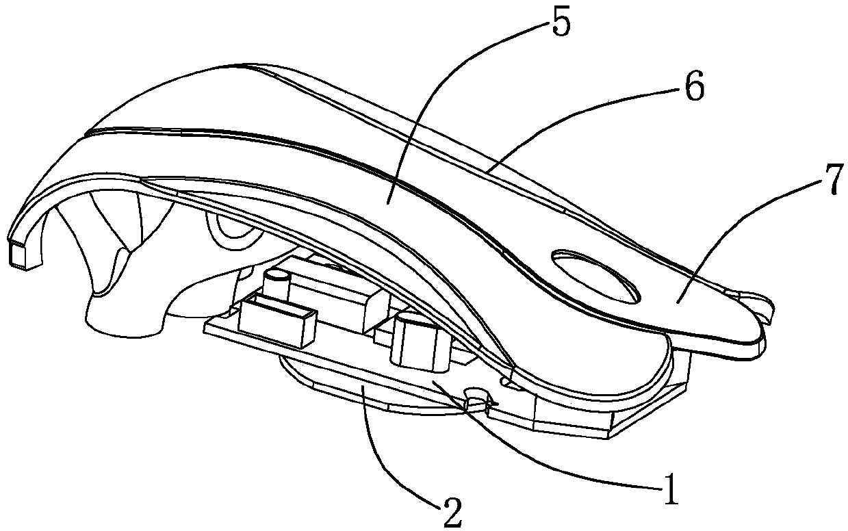
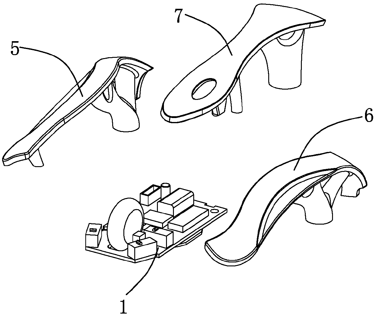
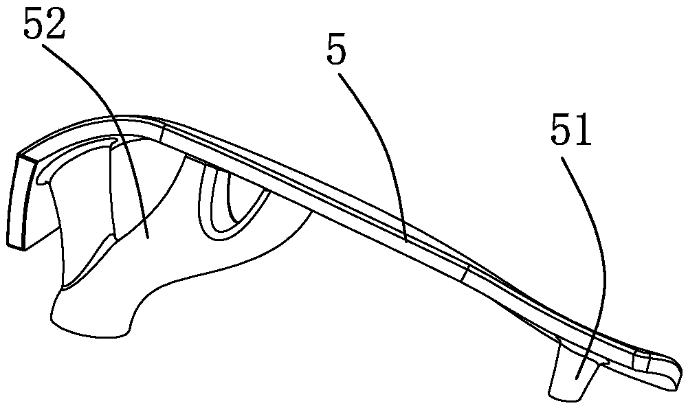
[0024] Embodiment: An electronic balance auxiliary module of an unmanned aerial vehicle, its main structure includes: flight control electronic board 1, metal sheet 2, roller 3, touch delayer 4, left wing frame plate 5, touch needle 51, rotor Connect the tail pipe 52, the right wing frame plate 6, the center board 7, connect the tail pipe 71, the electronic board hook rod 72, the roller clamping chamber 73, and the roller groove 74. The flight control electronic board 1 is adsorbed and fixed with a metal sheet 2. The left and right sides of the front end of the flight control electronic board 1 are welded with a touch delay device 4, and a roller 3 is installed between the two touch delay devices 4;

[0025] The left and right sides of the center plate 7 are respectively spliced ​​and fixed with a left wing frame plate 5 and a right wing frame plate 6; the front end of the center plate 7 is provided with a connecting tailpipe 71, and the rear end is provided with a roller clamp...


PUM


Abstract

The invention relates to an electronic balancing auxiliary module of an unmanned aerial vehicle. A metal sheet is adsorbed and fixed under a flight control electronic board. The left and right sides of the front end of the flight control electronic board are welded with a touch delay device and a roller is arranged between the two touch delay devices. A left wing frame plate and a right wing frameplate are respectively spliced and fixed on the left and right sides of the middle plate. The front end of the middle plate is provided with a connecting tail pipe, and the rear end is provided witha roller clamping cavity, and the roller clamping cavity is matched with the roller in the space position. The invention adopts a left wing frame plate and a right wing frame plate whose front ends are provided with touch needles, and rear ends are provided with rotor connection tail pipes; the touch needles are in conflict with the touch delay device; the rotor connection tail pipe of the left wing frame is connected to the electric adjustment module of the motor on the left side of the UAV; the rotor connecting tail pipe of the right wing frame is connected to the electric adjustment moduleof the motor on the right side of the UAV, realizing the manufacture of an electronic balance auxiliary module for a UAV.

Description

technical field [0001] The invention relates to an electronic balance auxiliary module of an unmanned aerial vehicle. Background technique [0002] The flight control system is the core system for the UAV to complete the entire flight process such as take-off, air flight, mission execution, and return to the field. The flight control system for UAVs is equivalent to the role of drivers for manned aircraft. One of the core technologies. Flight control generally includes three parts: sensors, onboard computers, and servo actuation equipment. The functions realized mainly include UAV attitude stabilization and control, UAV mission equipment management, and emergency control. The so-called flight control of UAV is the flight control system of UAV, mainly including gyroscope (flight attitude perception), accelerometer, geomagnetic induction flight, air pressure sensor (rough control of hovering height), ultrasonic sensor (low-altitude altitude accurate Control or obstacle avoid...

Claims


Application Information

Patent Timeline
Patent Type & Authority Applications(China)
IPC IPC(8): B64D31/06B64C27/08
CPCB64C27/08B64D31/06B64U10/10B64U50/19
Inventor 不公告发明人
Owner 胡铭
Why Eureka
Try Eureka