Eureka AIR delivers breakthrough ideas for toughest innovation challenges, trusted by R&D personnel around the world.

Slab mounting vehicle

A technology for installing carts and slats, applied in manipulators, manufacturing tools, construction, etc., can solve the problems of low adjustment accuracy, difficult to control speed, and large overall length of the manipulator, achieving compact structure, precise installation and alignment of slats, The effect of improving drive accuracy

Active Publication Date: 2019-01-22
广东永基建筑基础股份有限公司
View PDF6 Cites 5 Cited by
  • Summary
  • Abstract
  • Description
  • Claims
  • Application Information

AI Technical Summary

Problems solved by technology

It has the following defects: 1. The overall length of the body and the manipulator is too large, and it is difficult to operate normally in the messy and narrow working area of ​​the work surface, and the support structure must be added to the swing arm to bear the gravity of the manipulator and slats; 2. With pitch adjustment function
During the slat masonry construction process, the manipulator transports the slats to the masonry position. Before fixed placement, cleaning and plastering are required. In addition, when cross operations are encountered at the construction site, the front of the car body needs to be temporarily freed for other construction activities. In the above cases, the manipulator and other structures need to be lifted up temporarily; 3. All the adjustment mechanisms of the mechanical device are driven by oil cylinders, the adjustment accuracy is low, and the speed adjustment is difficult to control

Method used


Image

  • Slab mounting vehicle
  • Slab mounting vehicle

Examples


Embodiment Construction

[0025] The following will clearly and completely describe the technical solutions in the embodiments of the present invention with reference to the accompanying drawings in the embodiments of the present invention. Obviously, the described embodiments are only some, not all, embodiments of the present invention. Based on the embodiments of the present invention, all other embodiments obtained by persons of ordinary skill in the art without making creative efforts belong to the protection scope of the present invention.

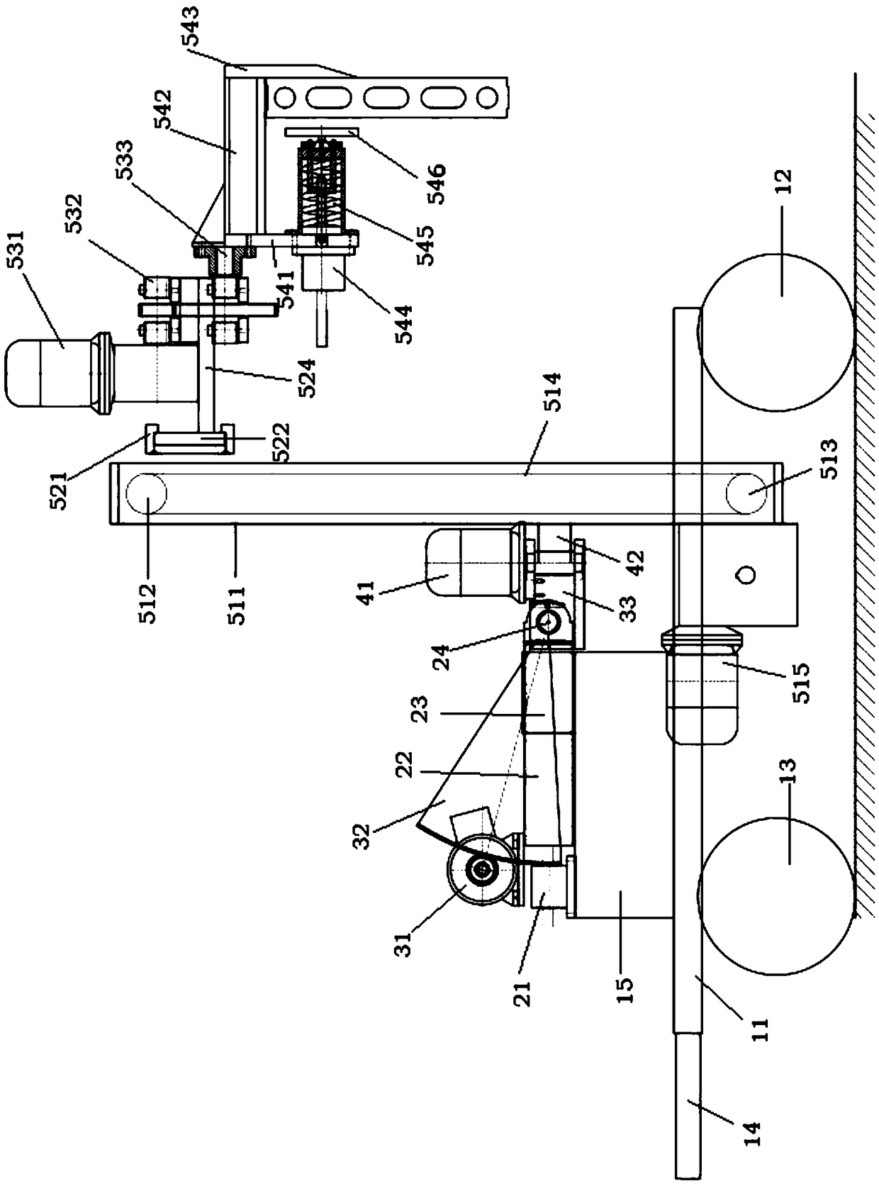
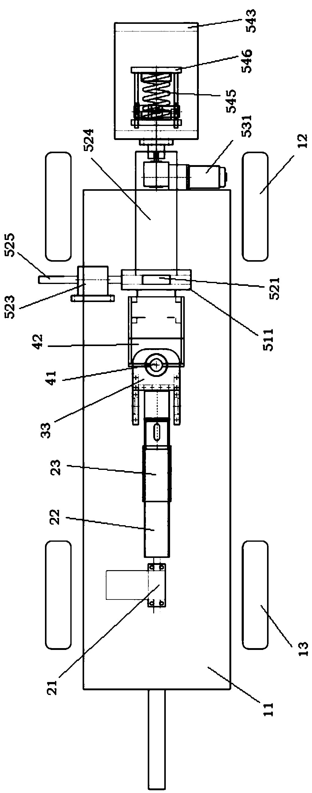
[0026] The object of the present invention is to provide a slat installation vehicle to solve the problems existing in the prior art. By integrating the distance adjustment mechanism, the pitch adjustment mechanism and the counterweight bearing platform, and connecting with the manipulator, the bearing platform is fixed on the On the frame between the front wheel and the rear wheel, the entire manipulator structure moves closer to the top of the car body table,...


PUM


Abstract

The invention discloses a slab mounting vehicle and belongs to the technical field of laying construction. The slab mounting vehicle comprises a vehicle body, a distance adjustment mechanism, a lifting adjustment mechanism and a slab mounting manipulator. A counterweight bearing platform is fixed on a frame between front wheels and rear wheels of the vehicle body, and the distance adjustment mechanism and the lifting adjustment mechanism are arranged on the counterweight bearing platform. The distance adjustment mechanism comprises a first driving device, a telescopic rod and a guide sleeve, and a horizontal rotating shaft is arranged at one end, far away from the distance adjustment device, of the telescopic rod. The lifting adjustment mechanism comprises a second driving device and a lifting drive part, and the slab mounting manipulator is fixedly arranged at one end, far away from the second driving device, of the lifting drive part. The slab mounting vehicle has the advantages thatthe distance adjustment mechanism and the lifting adjustment mechanism are integrally formed with the counterweight bearing platform and fixed on the frame between the front wheels and the rear wheels jointly, so that the vehicle body is compact in integral structure; the manipulator can ascend and descend partially through the lifting adjustment mechanism so as to spare the work plane for otherprocess steps and other work types.

Description

technical field [0001] The invention relates to the technical field of masonry construction, in particular to a batten installation vehicle. Background technique [0002] Concrete slats are a good material to replace building space partitions. They have the advantages of fast masonry speed, high flatness, and the elimination of secondary plastering and leveling. They meet the requirements of wall reform in the development of building industrialization. [0003] The traditional manual installation of concrete slats is not only slow in construction speed, but also difficult to control the horizontal and vertical accuracy, labor-intensive, and cannot effectively save resources and increase construction speed. Therefore, the mechanization of slat masonry construction is an urgent goal in this field . [0004] The patent with the application number CN201710470535.9 discloses a slat installation vehicle and its slat installation manipulator. The slat installation manipulator can ...

Claims


Application Information

Patent Timeline
Patent Type & Authority Applications(China)
IPC IPC(8): E04G21/16B25J11/00
CPCB25J11/00E04G21/167
Inventor 黎志中黎鹏斌
Owner 广东永基建筑基础股份有限公司
Why Eureka
Eureka Blog
Learn More