Harmonic reducer capable of being directly connected with a mechanical arm

A technology of harmonic reducer and manipulator, which is applied in the direction of manipulator, mechanical equipment, program control manipulator, etc. It can solve the problems of time-consuming tightening, low assembly efficiency, and limited rotation angle, so as to reduce production cost and improve product connection accuracy , Reduce the effect of shape and position tolerance

Pending Publication Date: 2019-01-22
杨庆华
View PDF22 Cites 1 Cited by
  • Summary
  • Abstract
  • Description
  • Claims
  • Application Information

AI Technical Summary

Problems solved by technology

In this assembly process, because the circumferential direction of the screw is released on the outside of the rigid wheel, its rotation angle is very limited, resulting in time-consuming tightening, resulting in low assembly efficiency
In addition, such a connection and assembly process will reduce the precision of the connection between the reducer flange and the connection flange and reduce the strength, resulting in a decrease in the overall quality of the mechanical arm.

Method used


Image

  • Harmonic reducer capable of being directly connected with a mechanical arm
  • Harmonic reducer capable of being directly connected with a mechanical arm
  • Harmonic reducer capable of being directly connected with a mechanical arm

Examples


Embodiment 1

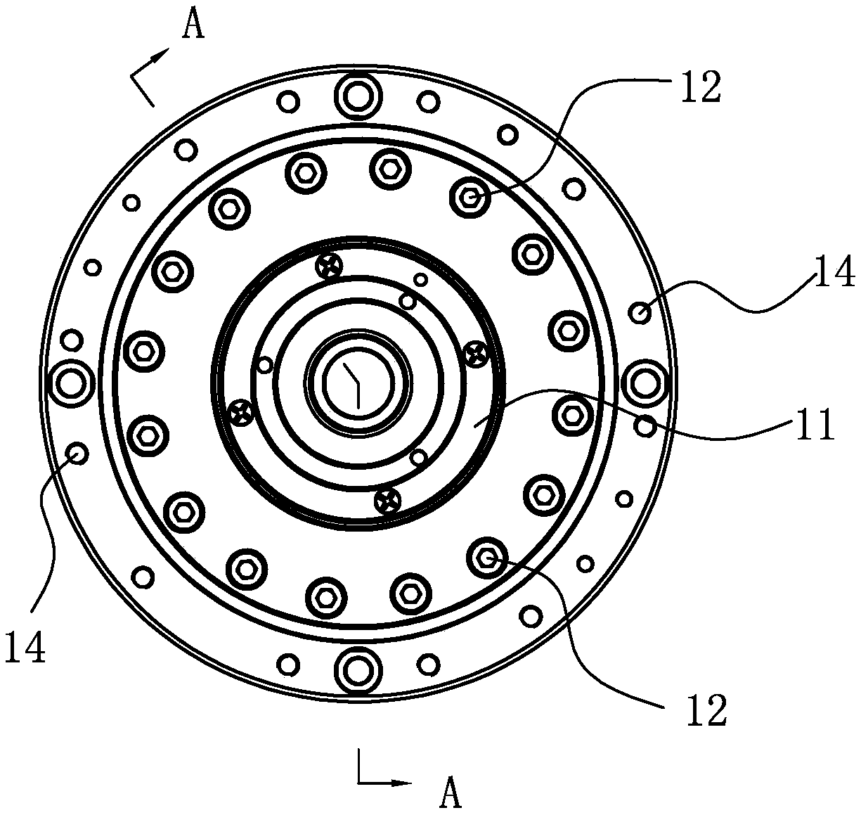
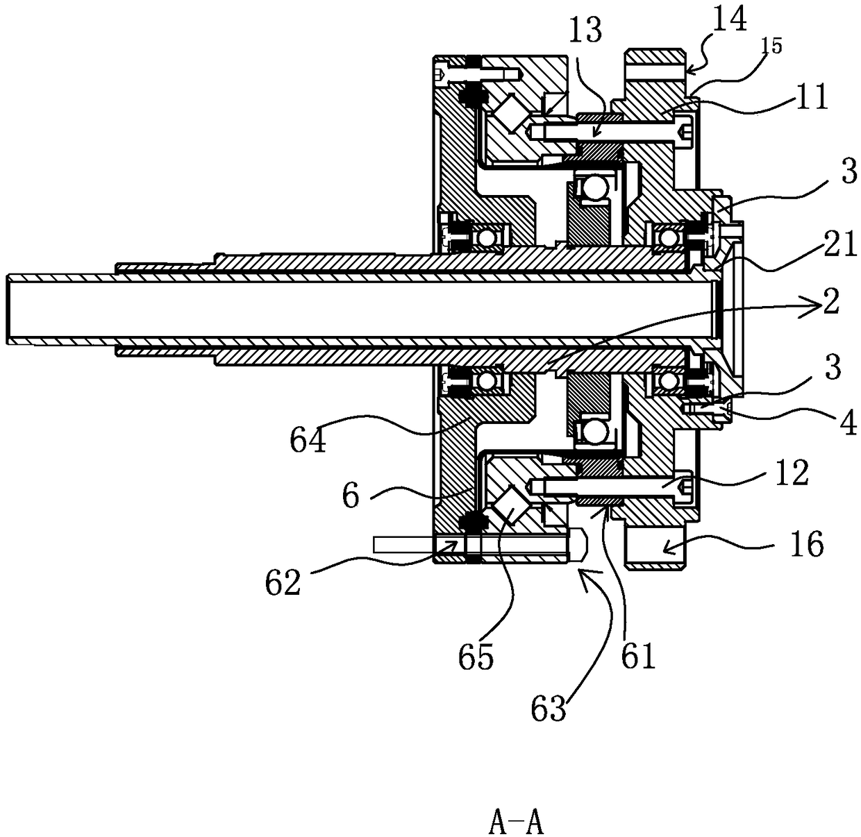
[0018] The rear end of the harmonic reducer 6 on the mechanical arm joint 1 of the present implementation has a rear end cover 11, and the rear end cover 11 has a plurality of circumferentially distributed rear end cover fixing screw holes 13. The harmonic reducer 6 The rigid wheel 61 on the top is also provided with the fixing screw hole corresponding to the rear end cover fixing screw hole 13, and the rear end cover 11 is fixed on the rigid wheel 61 by several rear end cover fixing screws 12; On the rear end cover 11, several circumferentially distributed rear end cover 11 connecting screw holes 14 are arranged to realize the output shaft load connection of the harmonic reducer 6, such as connections of mechanical arms, motors or jaws, etc., the rear end The cover connecting screw holes 14 are arranged in a circumferential direction on the rear end cover 11 .

[0019] The output shaft 2 of the mechanical arm joint 1 in this embodiment has a support rod 21, and the support ro...

Embodiment 2

[0021] The present embodiment is basically the same as embodiment one, except that the scheme of embodiment one also has the following characteristics:

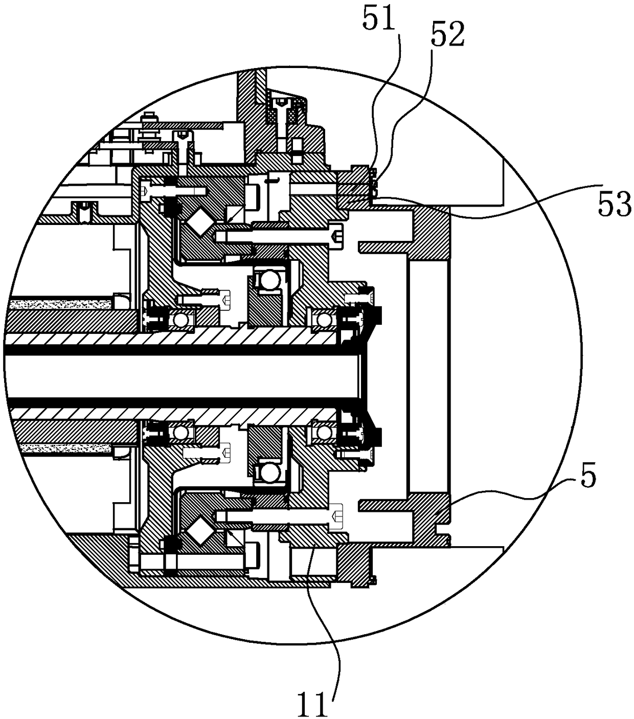
[0022] There is a rear end cover 11 on the rear end of the harmonic reducer 6 of the mechanical arm joint one of the present embodiment. The rear end cover 11 is provided with several connecting screw holes 14 distributed in the circumferential direction. Also be provided with step 15; Joint 2 5 has the joint 2 fixing hole 51 that is arranged correspondingly with connecting screw hole 14, is fixed in the connecting screw hole 14 by joint 2 fixing screw 52 through joint 2 fixing hole 51, thereby realizes rear The connection between end cap 11 and joint two 5.

[0023] The joint two 5 is also provided with a boss 53, the boss 53 is set in cooperation with the step 15, and the setting of the step 15 plays the role of connection and positioning between the rear end cover 11 and the joint two 5, and is a flange connecting with the...


PUM


Abstract

The invention relates to a harmonic reducer, and belongs to the field of manufacturing of mechanical arms. The harmonic reducer is provided, an output end is connected with joints at high precision, the joints are assembled conveniently, a rear end cap is arranged at the rear end of the harmonic reducer on a first mechanical arm joint, a plurality of rear end cap connecting screw holes which are distributed in the peripheral direction are formed in the rear end cap, and a step is further arranged at an end of the rear end cap; and a second joint fixing hole which corresponds to a connecting screw hole is formed in a second joint, a second joint fixing screw penetrates through the second joint fixing hole and is fixed in a connecting screw hole, and therefore, the rear end cap is connectedwith the second joint. The original traditional speed reducer flange plate connecting method is abandoned, thus, the harmonic reducer mechanism is compact and simple, form and location tolerance is relieved, an effect of improving the product connecting precision is achieved, and the production cost is reduced on the basis of reduction of accessories.

Description

technical field [0001] The application relates to a harmonic reducer that can be directly connected to a mechanical arm, and belongs to the field of mechanical arm manufacturing. Background technique [0002] The national invention patent (CN204604352) discloses a mechanical arm joint, wherein the shaft of the motor is hollow, the inner end of the output shaft is fixed to the output end of the harmonic reducer, and the outer end of the output shaft passes through the motor shaft At the outer end, a motor grating is fixed at the outer end of the motor shaft, an output shaft grating is fixed at the outer end of the output shaft, an encoder is fixed inside the housing, and the output shaft grating and the motor grating are respectively located on the upper and lower sides of the encoder. The upper and lower sides of the encoder are respectively equipped with photoelectric switches that cooperate with the output shaft grating and the motor grating. This invention has the advanta...

Claims


Application Information

Patent Timeline
Patent Type & Authority Applications(China)
IPC IPC(8): F16H49/00B25J9/10
CPCF16H49/001B25J9/1025
Inventor 杨庆华
Owner 杨庆华
Why Eureka
Try Eureka