
Torsion beam bushing assembly and method for making and installing the same

An installation method and technology of torsion beam, which are applied in vehicle parts, transportation and packaging, elastic suspension, etc., can solve problems such as affecting the performance of the whole vehicle, reliability noise, processing and assembly processes, and difficulty in ensuring shape and position tolerances. Achieve the effect of eliminating the risk of loosening, reducing the press-fitting process and reducing the cost

Inactive Publication Date: 2014-10-15
柳州孔辉汽车科技有限公司
View PDF5 Cites 0 Cited by
  • Summary
  • Abstract
  • Description
  • Claims
  • Application Information

AI Technical Summary

Problems solved by technology

[0005] 1) Mounting lug Ⅰ and mounting lug Ⅱ are press-fitted separately, and it is difficult to guarantee their shape and position tolerance;
[0006] 2) There are more processing and assembly processes, and the cost is higher;
[0007] 3) The installation lug I and the installation lug II cooperate with the inner sleeve through interference fit, and the force of this bush is very complicated, which may cause it to loosen, which will affect the performance, reliability and noise of the whole vehicle

Method used


Image

  • Torsion beam bushing assembly and method for making and installing the same
  • Torsion beam bushing assembly and method for making and installing the same
  • Torsion beam bushing assembly and method for making and installing the same

Examples


Embodiment Construction

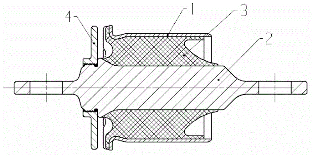
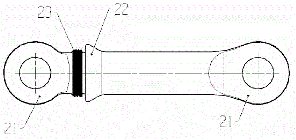
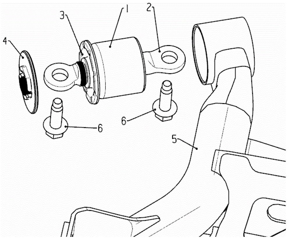
[0033] A torsion beam bushing assembly, such as figure 1 As shown, the torsion beam bushing assembly includes a bushing outer sleeve 1, an integral shaft-shaped bushing inner sleeve 2, a rubber material 3, and a limiting component 4. The integral shaft-shaped bushing inner sleeve 2 includes a lining One-piece parts including the inner sleeve and the lugs at both ends, such as figure 2 As shown, both ends of the integrated shaft-shaped bushing inner sleeve 2 are mounting lugs 21 with mounting holes, and between one end of the round shaft body and the mounting lugs is a conical transition section 22. The conical transition section There is a section of cylinder between 22 and the mounting ear plate 21, and an external thread 23 is opened on the cylinder, which is composed of a bushing outer sleeve 1, an integral shaft bushing inner sleeve 2 and filling in the bushing outer sleeve and the integral shaft bushing The rubber material 3 in the axial annular space between the sleeves ...


PUM


Abstract

A torsion beam bushing assembly, comprising a cylindrical bushing assembly with mounting lugs and a stop ring at one end of the cylindrical bushing assembly, the cylindrical bushing assembly with mounting lugs It is a one-piece component formed by vulcanizing the bushing outer casing, the integrated shaft-shaped bushing inner sleeve and the rubber material filled in the axial annular space between the bushing outer casing and the integrated shaft-shaped bushing inner sleeve. The one-piece shaft-shaped bush inner sleeve is an integral part including the bush inner sleeve and the lugs at both ends, and the stop ring is a flange with threads in the inner hole. In this state, the cylindrical bushing assembly is press-fitted onto the torsion beam through interference fit, and the limit ring is integrated with the integrated shaft-shaped bushing inner sleeve installed on the torsion beam through threaded connection. The torsion beam suspension using the torsion beam bushing assembly improves the assembly accuracy, the performance and reliability of the whole vehicle, and is convenient in processing, manufacturing and installation, and has low cost.

Description

technical field [0001] The invention belongs to auto parts and a manufacturing and installing method thereof, in particular to a torsion beam bushing assembly and a manufacturing and installing method thereof. Background technique [0002] The bushing of the torsion beam is a very important part of the torsion beam suspension. The torsion beam bushing plays the role of alleviating the vibration and impact from the road surface and ensuring the handling and stability; the guiding and buffering of the torsion beam suspension, etc. , is mainly transmitted through this bushing, therefore, the torsion beam bushing is a very complex component under stress. [0003] The existing torsion beam bushing structure such as Figure 4 Shown: It consists of outer cylinder 1a, inner sleeve 2a, rubber parts 3a, mounting lug I (4a) and mounting lug II (5a) with flange; as Figure 5 As shown, the assembly relationship is: part 3a is vulcanized together with part 1a and part 2a to form a small ...

Claims


Application Information

Patent Timeline
Patent Type & Authority Patents(China)
IPC IPC(8): B60G11/20
Inventor 赵亮黄振之胡少君李海建张宝霞
Owner 柳州孔辉汽车科技有限公司
Learn More