

Detection device for pressure container
A detection device and pressure vessel technology, applied in measuring devices, using stable tension/pressure to test the strength of materials, instruments, etc. uniform effect
- Summary
- Abstract
- Description
- Claims
- Application Information
AI Technical Summary
Problems solved by technology
Method used
Image

Examples
Embodiment 1
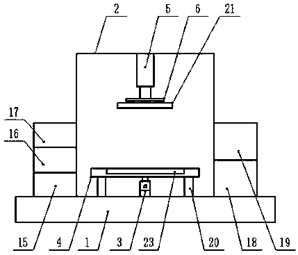
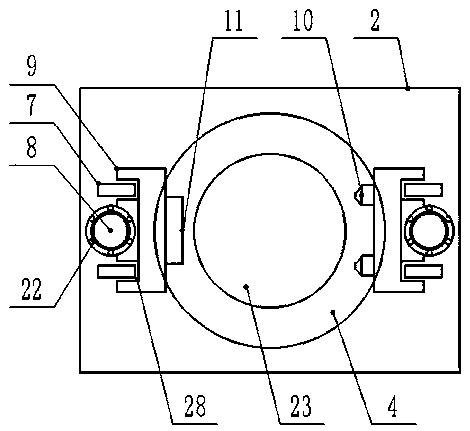
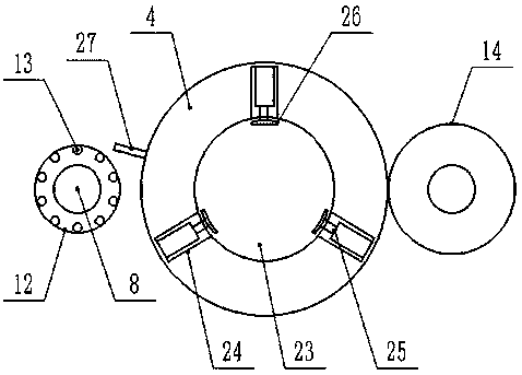
[0019] Embodiment 1: see figure 1 , figure 2 , image 3 , a detection device for a pressure vessel provided by the present invention will now be described, including a base base 1 and a detection box 2 provided in the middle of the upper end of the base base 1, and a rotating motor 3 is provided in the middle of the inner bottom of the detection box 2, The lower end of the inner cavity of the detection box 2 is provided with a support platform 4 above the rotating motor 3, and the middle part of the top of the detection box 2 is provided with a lifting cylinder 5, and the piston rod of the lifting cylinder 5 is vertically downward. The end is provided with a lifting platform 6, and the left and right ends of the inner chamber of the detection box 2 are provided with a set of vertical guide rails 7, and the middle part between the vertical guide rails 7 is respectively provided with a screw rod 8, and the outer parts of the screw rods 8 are respectively A sliding seat 9 is c...
Embodiment 2
[0020] Example 2: see figure 1 , a pressure vessel detection device provided by the present invention will now be described. A support column 20 is evenly arranged between the bottom end of the support table 4 and the inner bottom end of the detection box 2, and the top end of the support column 20 is The spheres are movable respectively, and the bottom end of the support table 4 is provided with a circular rolling groove corresponding to the distribution position of the spheres. The rotating motor 3 is located between the supporting columns 20, and the rotating motor 3 is vertically upward. The output shaft is connected with the middle part of the bottom end of the support platform 4, and the lower end of the lifting platform 6 is movable with a pressing plate 21 through a circular shaft.
Embodiment 3
[0021] Embodiment 3: see figure 1 , figure 2 , a pressure vessel detection device provided by the present invention will now be described. The front end of the detection box 2 is provided with a manual single-open door body, and the vertical guide rails 7 are arranged in parallel at intervals along the front and rear directions of the installation position of the detection box 2. , the middle part of the left and right sides of the detection box 2 is provided with the screw rod 8 along the vertical direction, and the slide seat 9 is provided with a guide groove 28 on one side and corresponding to the position of the vertical guide rail 7, Connecting pieces 22 are provided between the sliding seat 9 and the screw rod 8 respectively, and the connecting pieces 22 include a moving nut, a steel inner ring, a steel outer ring and rollers.
PUM
 Abstract
Description
Claims
Application Information