Steel vibration damper

A damper and buffer technology, used in shock absorbers, springs/shock absorbers, shock absorbers, etc., can solve problems such as damper damage, inability to meet high-precision use requirements, and prone to jitter, to ensure shock resistance. Effect

Pending Publication Date: 2022-03-01
TONGJI UNIV
View PDF0 Cites 0 Cited by
  • Summary
  • Abstract
  • Description
  • Claims
  • Application Information

AI Technical Summary

Problems solved by technology

The shock absorber based on the passive control mode is widely used due to its simple structure and low cost, but its damping and natural frequency cannot be adjusted. When the mode dampers are the same or close to each other, a better vibration reduction effect can be achieved; when the natural frequency and the excitation frequency differ greatly, the vibration reduction effect will be poor or even the vibration will deteriorate
Today's steel vibration dampers have poor seismic performance and are prone to vibration problems, which cannot meet the high-precision use requirements, and the buffering and shock absorption effects need to be improved, and high-intensity impacts will cause damage to the damper

Method used


Image

  • Steel vibration damper
  • Steel vibration damper
  • Steel vibration damper

Examples


Embodiment Construction

[0019] In order to make the objectives, technical solutions and advantages of the present invention clearer, the present invention will be described in further detail below in conjunction with the accompanying drawings and embodiments, and the technical solutions in the embodiments of the present invention will be clearly and completely described. Obviously, the described The embodiments are only some of the embodiments of the present invention. It should be understood that the specific embodiments described here are only used to explain the present invention, not to limit the present invention. rather than all examples.

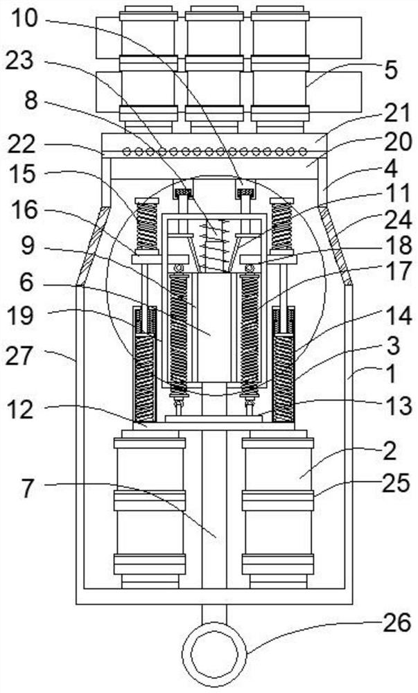
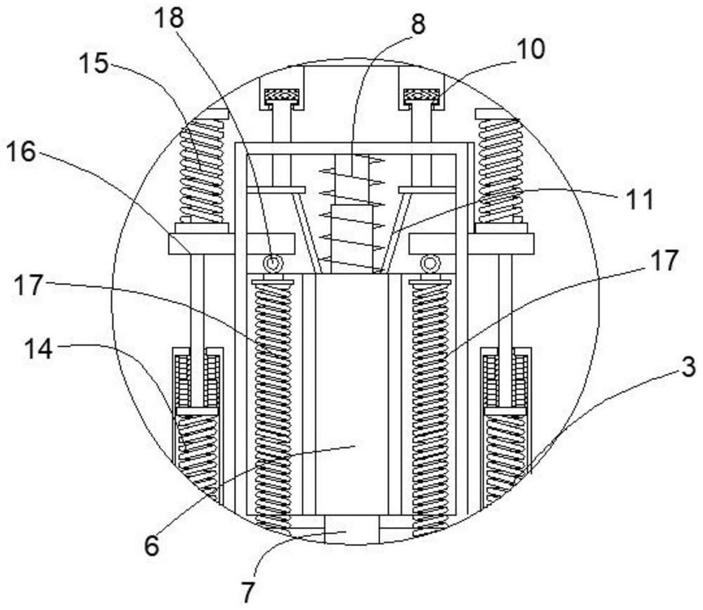
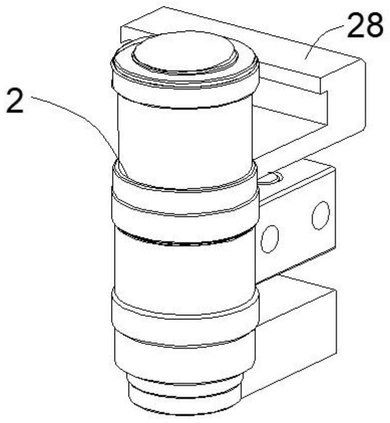
[0020] Such as Figure 1-3 As shown, the present invention provides a technical solution: a steel vibration damper, including a bottom cylinder 1, an installation area is provided inside the bottom cylinder 1, and an inner piston cylinder assembly 2 is arranged in the installation area. The upper part of the inner piston cylinder assembly 2 is provided wit...


PUM


Abstract

The invention discloses a steel vibration damper which comprises a bottom cylinder, an installation area is arranged in the bottom cylinder, an inner piston cylinder assembly is arranged in the installation area, a vibration buffering part is arranged on the upper portion of the inner piston cylinder assembly, a top sleeve is arranged on the vibration buffering part in a sleeving mode, and an outer piston cylinder assembly is arranged on the upper portion of the top sleeve. The inner piston cylinder assembly and the vibration buffering part are located in the mounting area, the vibration buffering part comprises a compression cylinder, a connecting rod is movably inserted into the bottom of the compression cylinder, one end of the connecting rod is movably connected into the compression cylinder, and the other end of the connecting rod penetrates through the bottom cylinder and extends out of the bottom cylinder; the compression cylinder is sleeved with a limiting installation piece, and a compressible abutting piece is arranged on the upper portion of the limiting installation piece. According to the steel vibration damper, through the arrangement of the bottom cylinder, the inner piston cylinder assembly, the vibration buffering part, the top sleeve and the outer piston cylinder assembly, the buffering, damping and compression resisting effects are achieved, and the shock resistance of the dynamic damper is guaranteed.

Description

technical field [0001] The invention relates to the technical field of dampers, in particular to a steel vibration damper. Background technique [0002] A damper is a device that provides resistance to movement and consumes movement energy. Various dampers (or shock absorbers) have been used in industries such as aerospace, aviation, military industry, guns, and automobiles to reduce vibration and energy. People began to gradually transfer damper technology to structural engineering such as buildings, bridges, and railways, and its development was very rapid. In particular, the hydraulic viscous damper with a history of more than 50 years has gone through a lot of experiments, strict examinations, repeated demonstrations, and especially a long process of earthquake tests before being accepted by the structural engineering community in the United States. A device capable of rapidly stopping the movable part of an instrument in a stable deflected position. In seismic instru...

Claims


Application Information

Patent Timeline
Patent Type & Authority Applications(China)
IPC IPC(8): F16F13/00E04B1/98E04H9/02
CPCF16F13/005E04B1/98E04H9/021E04H9/023E04H9/0237
Inventor 朱亚智温永昕王鹏蔡小宁
Owner TONGJI UNIV
Why Eureka
Try Eureka