Eureka AIR delivers breakthrough ideas for toughest innovation challenges, trusted by R&D personnel around the world.

Tube-in-tube bridge tower of space hybrid cable net suspension bridge with parabolic arched tower cap

A space-mixing, tube-in-tube technology, applied to suspension bridges, bridges, bridge parts, etc., can solve the problems of not being able to meet the wind resistance stability requirements, lateral stiffness and torsional stiffness of 4,000-meter-class super-long-span suspension bridges across the Strait, etc. Achieve the effect of increasing the critical wind speed of flutter, improving the anti-seismic performance, and ensuring the stability of wind resistance

Pending Publication Date: 2019-06-18
江苏交通工程咨询监理有限公司
View PDF0 Cites 6 Cited by
  • Summary
  • Abstract
  • Description
  • Claims
  • Application Information

AI Technical Summary

Problems solved by technology

[0005] The traditional suspension bridge pylon structure, equipped with two parallel steel wire cables on the left and right, can bear the vertical load of the suspension bridge with a span of 4000 meters. However, due to the poor lateral stiffness and torsional stiffness of the vertically parallel cable system, it cannot meet the requirements. Wind Stability Requirements for 4000m Class Super Long Span Strait Suspension Bridge

Method used


Image

  • Tube-in-tube bridge tower of space hybrid cable net suspension bridge with parabolic arched tower cap
  • Tube-in-tube bridge tower of space hybrid cable net suspension bridge with parabolic arched tower cap
  • Tube-in-tube bridge tower of space hybrid cable net suspension bridge with parabolic arched tower cap

Examples


Embodiment Construction

[0033] The present invention will be further described below in conjunction with the accompanying drawings and specific embodiments.

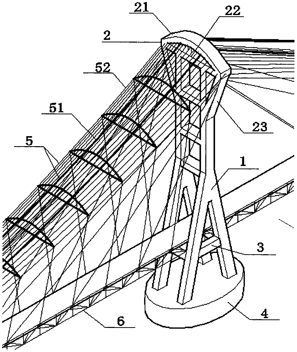
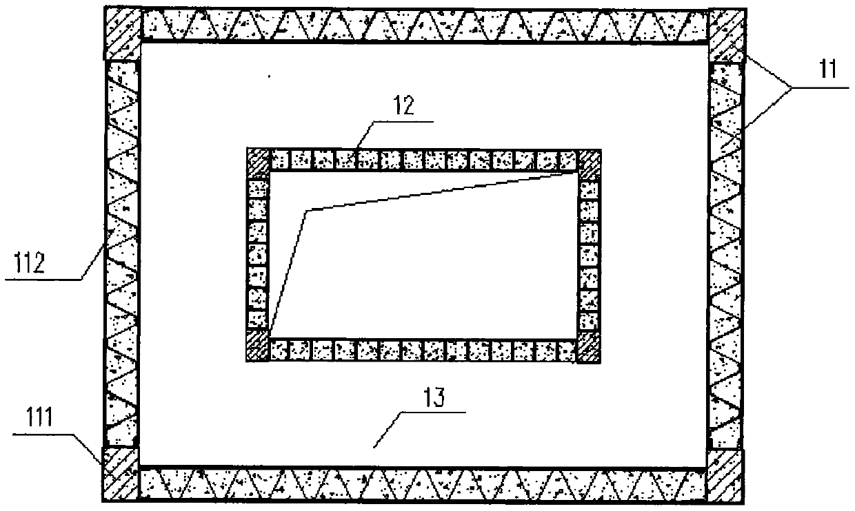
[0034] A tube-in-tube bridge tower of a space hybrid cable-net suspension bridge with a parabolic arched tower cap of the present invention includes a tube-in-tube herringbone tower column 1 and a parabolic arched tower cap 2, and the tube-in-tube herringbone tower column 1 Composed of an outer tube structure 11, a core tube structure 12 and several rigid diaphragms 13, a tube-in-tube herringbone column 1 is arranged on the left and right sides of the suspension bridge tower, and the parabolic arched tower cap 2 is composed of a giant Parabolic arch 21, giant rigid tie rod 22 and giant diagonal brace 23 are composed of three. The giant parabolic arch 21 is placed on two tube-in-tube herringbone towers 1 in the way of cantilever at both ends. The end arch feet are connected by a huge rigid tie rod 22, one end of the giant diagonal brace 23 is an...


PUM


Abstract

The invention provides a tube-in-tube bridge tower of a space hybrid cable net suspension bridge with a parabolic arched tower cap. The tube-in-tube bridge tower of the space hybrid cable net suspension bridge with the parabolic arched tower cap is characterized in that the parabolic arched tower cap with a rigid tie rod is arranged at the top of a tube-in-tube herringbone tower column; one end ofa giant diagonal bracing is anchored to the waist of the tube-in-tube herringbone tower column; the giant diagonal bracing supports the arch foot of the parabolic arched tower cap and forms a racket-like bridge tower structure; a load-bearing steel cable is placed on the tube-in-tube herringbone tower column, and a carbon fiber space cable net is anchored on the parabolic arched tower cap to enhance the spatial stiffness of the suspension bridge and realize the cooperation between two groups of cables; a concrete-filled rectangular steel tube corner column and a grille tubular double-steel concrete composite shear wall are adopted to form a tube structure; the tube-in-tube herringbone tower column comprises an outer tube structure, a core tube structure and multiple rigid diaphragms. Thetube-in-tube bridge tower of the space hybrid cable net suspension bridge with the parabolic arched tower cap has various advantages, such as strong structural rigidity, good wind resistance stability, rich facade modeling, strong earthquake resistance, and capability of being adopted as a bridge tower structure of a space cable net suspension bridge with a super-long span of 4000 meters.

Description

technical field [0001] The invention relates to the field of bridge engineering, and relates to a suspension bridge pylon structure of a super-long-span bridge, in particular to a tube-in-tube pylon structure of a space hybrid cable-net suspension bridge with a parabolic arched pylon cap. Background technique [0002] With the development of transportation, the span records of modern suspension bridges are constantly being refreshed. In the near future, humans will build 4,000-meter-class super-long-span suspension bridges across the Strait. [0003] With the increase of the span of the suspension bridge, the width-span ratio of the suspension bridge is continuously reduced, the structure of the suspension bridge is becoming softer and softer, the spatial stiffness of the super-long-span suspension bridge is continuously decreasing, and it is more sensitive to the wind, which leads to the continuous improvement of the wind-resistant stability of the super-long-span suspension...

Claims


Application Information

Patent Timeline
Patent Type & Authority Applications(China)
IPC IPC(8): E01D19/14E01D11/02E01D21/00
Inventor 徐金法
Owner 江苏交通工程咨询监理有限公司
Why Eureka
Eureka Blog
Learn More