Compression-resistant optical cable

An optical cable and cable core technology, which is applied to insulated cables, communication cables, flat/ribbon cables, etc., can solve the problems of increasing resources and waste, and achieve the effect of simple production process, resource saving and easy operation.

Inactive Publication Date: 2013-10-23
苏州天盛电线电缆有限公司
View PDF4 Cites 0 Cited by
  • Summary
  • Abstract
  • Description
  • Claims
  • Application Information

AI Technical Summary

Problems solved by technology

[0002] At present, there are many compression cables on the market. Most of them just make the cable sheath into a flat or oval cross-section during the production process. The sheath is braced into a circle or there are more gaps around the sheath, so that the cable cannot really play a role in compressive resistance, and it will also increase the waste of resources

Method used


Image

  • Compression-resistant optical cable

Examples


Embodiment

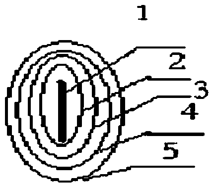
[0019] Such as figure 1 A kind of anti-pressure optical cable shown, it comprises flat cable core 1, insulator 2, inner sheath 3, armouring 4, outer sheath 5, wherein, flat cable core comprises optical fiber and metal wire, described optical fiber and The metal wires are interwoven and pressed into a flat shape; the flat cable core 1 is wrapped by the insulator 2, the inner sheath 3 is wrapped on the surface of the insulator 2, and the armor 4 is arranged on the inner sheath 3 and the outer sheath 5; the inner sheath, the armor, and the outer sheath are all set to a flat shape matched with the cable core, and the outer sheath 5 is a thin copper strip, which is connected with the armor 4 Form an integrated shielding layer.

[0020] The present invention when making, its concrete steps are as follows:

[0021] a. First, the optical fiber and the metal wire are twisted through a stranding machine, and then pressed into a flat cable core 1 through an extrusion machine;

[0022]...


PUM


Abstract

The invention discloses a compression-resistant optical cable, which comprises a flat cable core, an insulator, an inner sheath, an armor and an outer sheath, wherein the flat cable core is wrapped by the insulator; the inner sheath is wrapped on the surface of the insulator; the armor is arranged between the inner sheath and the outer sheath; the flat cable core comprises an optical fiber and a metal lead; the optical fiber and the metal lead are compressed to be flat after being interlaced; and the inner sheath, the armor and the outer sheath are of flat structures which are matched with the cable core. The compression-resistant optical cable has the advantages of real realization of compression resisting effect, simple manufacturing process, easiness in operating, capability of realizing large-scale production and saving in resources.

Description

technical field [0001] The invention relates to a cable, in particular to a pressure-resistant optical cable. Background technique [0002] At present, there are many compression-resistant cables on the market. Most of them just make the cable sheath into a flat or elliptical structure in the cross-section during the production process, and wrap the circular cable core in the flat sheath. The sheath is braced in a circular shape or there are more gaps around the sheath, so that the cable cannot really play a role in resisting compression, and it will also increase the waste of resources. Contents of the invention [0003] Purpose of the invention: the purpose of the present invention is to provide a kind of in order to solve the deficiencies in the prior art. [0004] Technical solution: In order to achieve the above purpose, a pressure-resistant optical cable according to the present invention includes: a flat cable core, an insulator, an inner sheath, armor, and an ou...

Claims


Application Information

Patent Timeline
IPC IPC(8): H01B7/00H01B7/08H01B7/17H01B11/22H01B13/00
Inventor 许斌
Owner 苏州天盛电线电缆有限公司
Why Eureka
Try Eureka