Eureka AIR delivers breakthrough ideas for toughest innovation challenges, trusted by R&D personnel around the world.

Limiting device for hammer mill and facilitating hammer replacement

A hammer mill, a technology that is easy to replace, applied in the direction of grain processing, etc., can solve the problems of no specific guidance plan, regular replacement, and more materials, so as to save time and effort for hammer replacement, reduce workload, The effect of improving work efficiency

Active Publication Date: 2019-01-25
HEBEI YUANDA SHUANGXUAN FODDER MACHINERY
View PDF10 Cites 2 Cited by
  • Summary
  • Abstract
  • Description
  • Claims
  • Application Information

AI Technical Summary

Problems solved by technology

[0003] As far as the current way of replacing the hammer is concerned, there are mainly the following disadvantages: ① Due to the arrangement of the hammers, hammer spacers of different lengths are required, and there are many materials to be prepared; ② Because the distance between the hammer spacers and the material layer is not If it is too far away, it is easy to wear and needs to be replaced regularly; ③ When replacing the hammer or adjusting the gap between the hammer and screen, slowly pull the hammer shaft away, remove the hammer and hammer spacer one by one, and install them one by one Press up, and also need to pay attention to the length of the hammer spacer
[0005] The above-mentioned technologies are how to make the limit device for easy replacement of the hammer so that the position of the hammer can be limited without the hammer spacer, and the limit device will not need to be replaced due to wear, and there is no need to replace the limit device when replacing the hammer The device is disassembled, saving time and effort, and no specific guidance plan is given

Method used


Image

  • Limiting device for hammer mill and facilitating hammer replacement
  • Limiting device for hammer mill and facilitating hammer replacement
  • Limiting device for hammer mill and facilitating hammer replacement

Examples


Embodiment 1

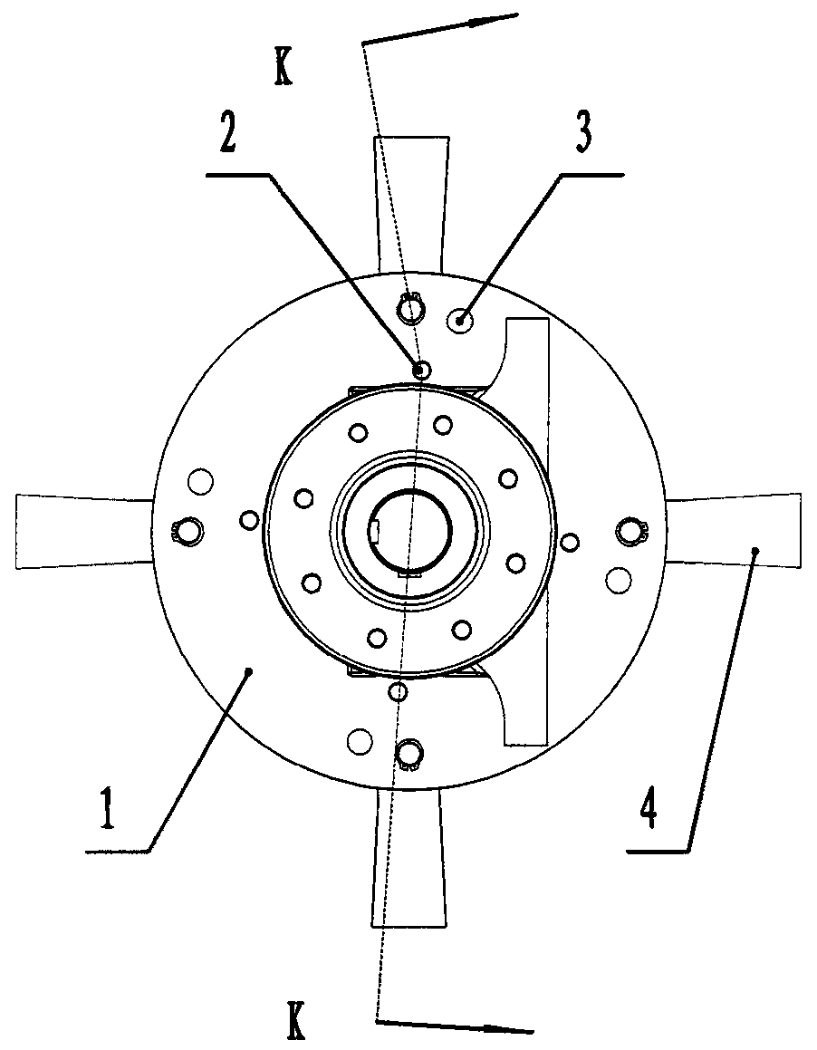
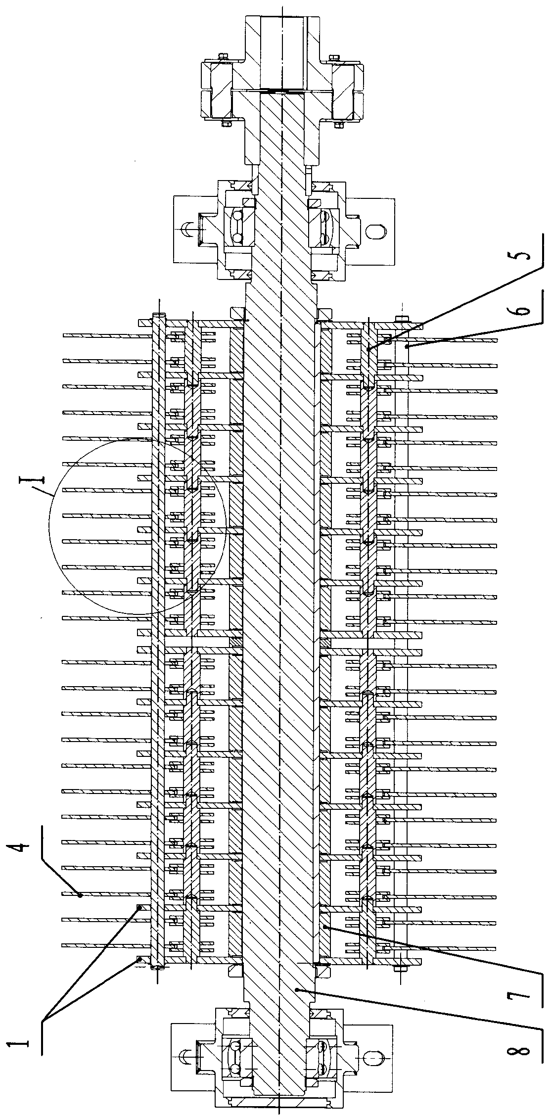
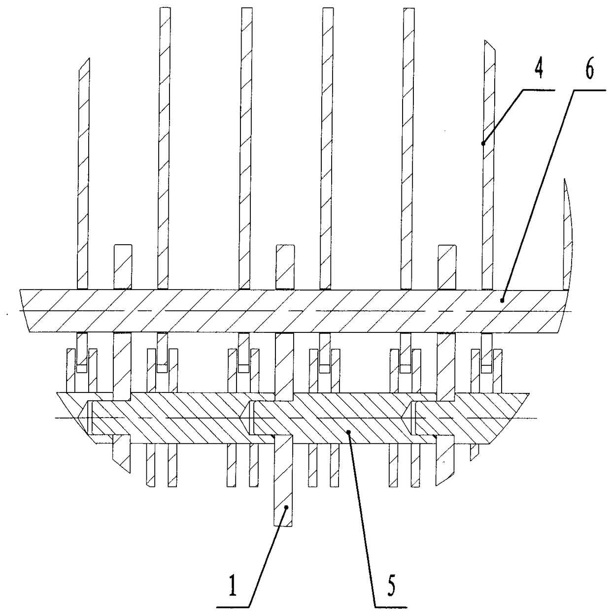
[0028] Embodiment 1: as figure 1 , figure 2 , image 3 , Figure 4 , Figure 5 , Image 6 , Figure 7 , Figure 8 As shown, the stopper for convenient replacement of the hammer for the hammer mill of the present invention has a plurality of hammer holders 1, a plurality of hammer shafts 6, a plurality of hammers 4, and a plurality of hammers are carried out. The limiting body 5 of the limit. Each hammer frame 1 has a group of hammer shaft holes (a group of hammer shaft holes) that make the hammer shaft in one installation position, and each group of hammer shaft holes on each hammer frame has a set of hammer shaft holes for A plurality of hammer shaft holes 3 corresponding to the plurality of hammer shafts passing through the plurality of hammer shafts, the number of the plurality of hammer shaft holes in each group of hammer shaft holes is the same as the number of hammer shafts , the projections of the transverse centerlines of the plurality of hammer axis holes 3 i...

Embodiment 2

[0034] Embodiment 2: as figure 1 , figure 2 , image 3 , Figure 4 , Figure 5 , Image 6 , Figure 7 , Figure 8 As shown, the stopper for convenient replacement of the hammer for the hammer mill of the present invention has a plurality of hammer holders 1, a plurality of hammer shafts 6, a plurality of hammers 4, and a plurality of hammers are carried out. The limiting body 5 of the limit. Each hammer frame 1 has two groups of hammer shaft holes (two groups of hammer shaft holes) that make the hammer shafts in two (different) installation positions respectively. Each group of hammers on each hammer frame The shaft hole has a plurality of hammer shaft holes 3 corresponding to the plurality of hammer shafts passing through the hammer shafts, and the number of the plurality of hammer shaft holes in each group of hammer shaft holes is the same as that of the hammer shaft. The number of film shafts is the same, and the projections of the transverse centerlines of the plu...


PUM


Abstract

A limiting device for a hammer mill and facilitating hammer replacement comprises hammer frames, hammer shafts, hammers and a limiting body. The limiting body is provided with a plurality of limitingrod members, each limiting rod member is formed by a plurality of limiting rod member units, and each limiting rod member unit is provided with a plurality of non-tail end limiting shafts, a tail endlimiting shaft and a plurality of pairs of limiting discs. The outer surface of each non-tail end limiting shaft and the outer surface of the tail end limiting shaft are respectively provided with theplurality of pair of limiting discs. One end of each non-tail end limiting shaft is provided with a shaft head, and the other end is provided with a shaft hole. Both ends of the tail end limiting shaft are provided with a shaft head. Each hammer frame is provided with a plurality of positioning holes. A combined connection structure of the limiting rod member units is provided, and the inner protruding end of each hammer is located in a compartment between the corresponding pair of limiting discs. The positions of the hammers can be limited without the need of a hammer spacer. When the hammers are replaced, the limiting device does not need to be removed. The replacement of the hammers is more convenient, the hammer replacement time is reduced, and the workload is reduced.

Description

technical field [0001] The invention relates to a hammer-type pulverizer, in particular to a position-limiting device for the hammer-type pulverizer which is convenient for replacing the hammer. Background technique [0002] The inventor finds by visiting the market that the hammer blade installation method of the present hammer mill is still traditional. That is to say, the hammer shaft is fixed on the hammer rack through the hammer shaft holes on several hammer racks. Several hammers are located on the hammer shaft. The hammer spacer (i.e., a round tube whose inner diameter is larger than the hammer shaft) separates it. [0003] As far as the current way of replacing the hammer is concerned, there are mainly the following disadvantages: ① Due to the arrangement of the hammers, hammer spacers of different lengths are required, and there are many materials to be prepared; ② Because the distance between the hammer spacers and the material layer is not If it is too far away,...

Claims


Application Information

Patent Timeline
Patent Type & Authority Applications(China)
IPC IPC(8): B02C13/28
CPCB02C13/28
Inventor 崔英辉丁寅赵志辉李瑞鹏
Owner HEBEI YUANDA SHUANGXUAN FODDER MACHINERY
Why Eureka
Eureka Blog
Learn More