High-precision hobbing clamp for gears and application method thereof

A gear hobbing jig, high-precision technology, applied in the field of high-precision gear hobbing jigs, can solve the problems of time-consuming and labor-intensive, multiple steps for clamping and disassembling gears, and achieve simple operation, low skill requirements, and time-saving disassembly Labor-saving effect

Active Publication Date: 2019-01-25
重庆市永和直锥齿有限公司
View PDF9 Cites 0 Cited by
  • Summary
  • Abstract
  • Description
  • Claims
  • Application Information

AI Technical Summary

Problems solved by technology

Its disadvantages are as follows: First, there are many steps for clamping and dismounting the gear, and each step requires manual operation, which is time-consuming and labor-intensive; second, the clamp needs steel balls to center the gear without supporting it during the clamping process. tight clamping requirements, which requires operators to have high operating experience

Method used


Image

  • High-precision hobbing clamp for gears and application method thereof
  • High-precision hobbing clamp for gears and application method thereof
  • High-precision hobbing clamp for gears and application method thereof

Examples


Embodiment 1

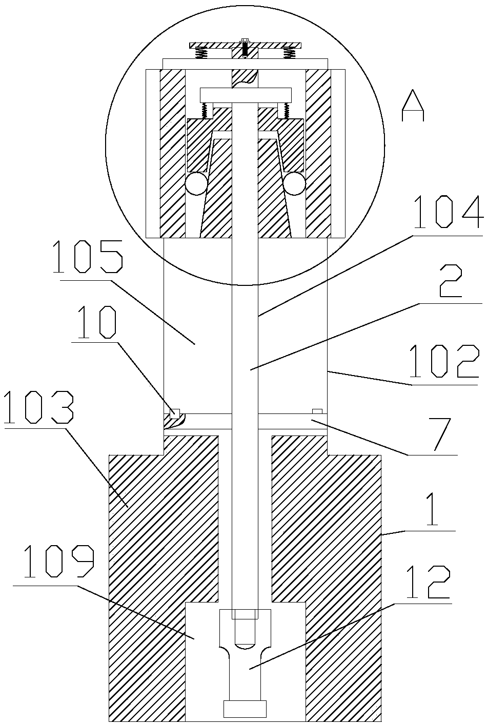
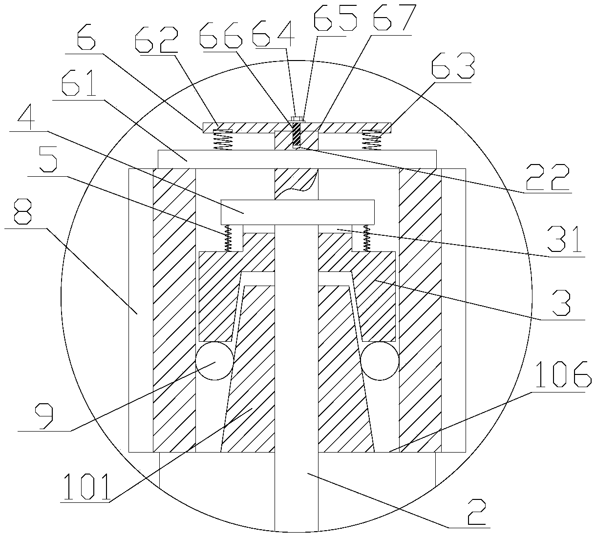
[0013] Embodiment 1: with reference to attached Figure 1-Figure 5 . A gear high-precision hobbing fixture, including a cone seat 1, the cone seat 1 is composed of a conical shaft section 101, a first circular shaft section 102 and a second circular shaft section 103 arranged in sequence from top to bottom and The centerlines of the tapered shaft section 101, the first circular shaft section 102, and the second circular shaft section 103 coincide, and the tapered shaft section 101, the first circular shaft section 102, and the second circular shaft section 103 are in the form of Overall structure and the diameter of the first circular shaft section 102 is greater than the diameter of the largest circle of the tapered shaft section 101 and the diameter of the first circular shaft section 102 is smaller than the diameter of the second circular shaft section 103, the cone The upper end surface of the seat 1 is provided with a through hole 104 passing through the upper and lower ...

Embodiment 2

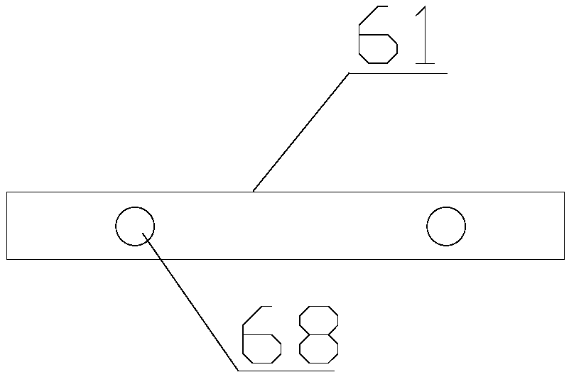
[0014] Embodiment 2: On the basis of Embodiment 1, a method of using a high-precision gear hobbing jig, step 1, before the gear 8 is hobbed, the first pressure plate 61 of the elastic pressure plate 6 is first passed through the pressure plate Pull out the hole 23, then place the gear 8 on the first shoulder 106 of the cone seat 1, then start the hydraulic lifting mechanism, and the hydraulic lifting mechanism drives the threaded connecting rod 12 to go up until the top sleeve 3 leaves the inner hole of the gear 8 and the gear 8 is on the The gap between the end surface and the lower end surface of the top sleeve 3 can pass through the steel ball 9; Step 2, put the steel ball 9 into the gap between the upper end surface of the gear 8 and the lower end surface of the top sleeve 3 and insert the first pressure plate 61 back into the pressure plate through the gap. In the hole 23, start the hydraulic lifting mechanism afterwards, and the hydraulic lifting mechanism drives the thre...


PUM


Abstract

The invention relates to a high-precision hobbing clamp for gears and an application method thereof. The upper end face of a conical seat is provided with a through hole; a slide rod is arranged in the through hole; a shank of the slide rod is sleeved with an ejector sleeve; a circular presser plate is welded or screwed to the shank of the slide rod; a plurality of elastic pull cords are vertically arranged between the circular presser plate and the ejector sleeve, the upper ends of the elastic pull rods are fixedly connected with the lower end face of the circular presser plate, and the lowerends of the elastic pull rods are fixedly connected with the upper end face of the ejector sleeve; an elastic presser plate is arranged at the upper end of the slide rod; the front of a first circular shaft segment is provided with an elongated through hole; the front of the slide rod is provided with a square hole, and a square rod is arranged in the square hole; a gear is mounted on the upper end face of the first shaft shoulder; a plurality of steel balls are arranged between the inner wall of the gear and the outer wall of a conical shaft segment; an ejector rod is arranged on each side of the upper end face of the square rod. The high-precision hobbing clamp for gears is simple to operate, has low requirement on a user's application skills, and takes less time and manpower for clamping and demounting.

Description

technical field [0001] The invention relates to a gear that not only realizes double-pressing gear clamping in one step and saves time and effort, but also realizes quick disassembly of the gear in one step, saves time and effort, and at the same time has high centering precision and good safety in use. A high-precision gear hobbing fixture and a using method thereof belong to the field of gear fixture manufacturing. Background technique [0002] CN 104759706A, titled "a tooling fixture for gear hobbing", including a base plate, a mandrel, a pad cover and a tooling assembly, the bottom end of the mandrel is plugged and fixed on the base plate, and the tooling assembly and the pad cover are set sequentially On the mandrel, the bottom surface of the pad sleeve is against the bottom plate, and the tooling assembly includes a fixed taper sleeve and a top sleeve, the fixed taper sleeve is located on the top surface of the pad sleeve, the fixed taper sleeve is plugged into the top...

Claims


Application Information

Patent Timeline
Patent Type & Authority Applications(China)
IPC IPC(8): B23F23/06
CPCB23F23/06
Inventor 郑煌
Owner 重庆市永和直锥齿有限公司
Why Eureka
Try Eureka