Eureka AIR delivers breakthrough ideas for toughest innovation challenges, trusted by R&D personnel around the world.

Ore processing milling device

A milling device and ore technology, applied in the field of ore processing, can solve the problems of low milling efficiency, high labor intensity, complicated operation, etc., and achieve the effect of high milling efficiency, low labor intensity and simple operation

Inactive Publication Date: 2019-01-25
安徽捷运矿山机械有限公司
View PDF9 Cites 1 Cited by
  • Summary
  • Abstract
  • Description
  • Claims
  • Application Information

AI Technical Summary

Problems solved by technology

[0003] When the existing ore is milled, most of the ore is fixed by the fixture, and then the milling cutter rotates as the main movement, and the ore moves as the feed movement, so that the milling cutter can mill the ore to cut out the required shape and characteristics. , after milling, if you need to mill the other side of the ore, you need to remove the ore from the fixture first, then place the end of the ore to be milled under the milling cutter, and then use the fixture to fix the ore , this kind of operation mode, in the process of milling, requires the operator to frequently disassemble the ore and then replace the different processing surfaces of the ore, which makes the operation complicated, labor-intensive, and the milling efficiency is low

Method used


Image

  • Ore processing milling device
  • Ore processing milling device
  • Ore processing milling device

Examples


Embodiment Construction

[0020] The following will clearly and completely describe the technical solutions in the embodiments of the present invention with reference to the accompanying drawings in the embodiments of the present invention. Obviously, the described embodiments are only some, not all, embodiments of the present invention. Based on the embodiments of the present invention, all other embodiments obtained by persons of ordinary skill in the art without making creative efforts belong to the protection scope of the present invention.

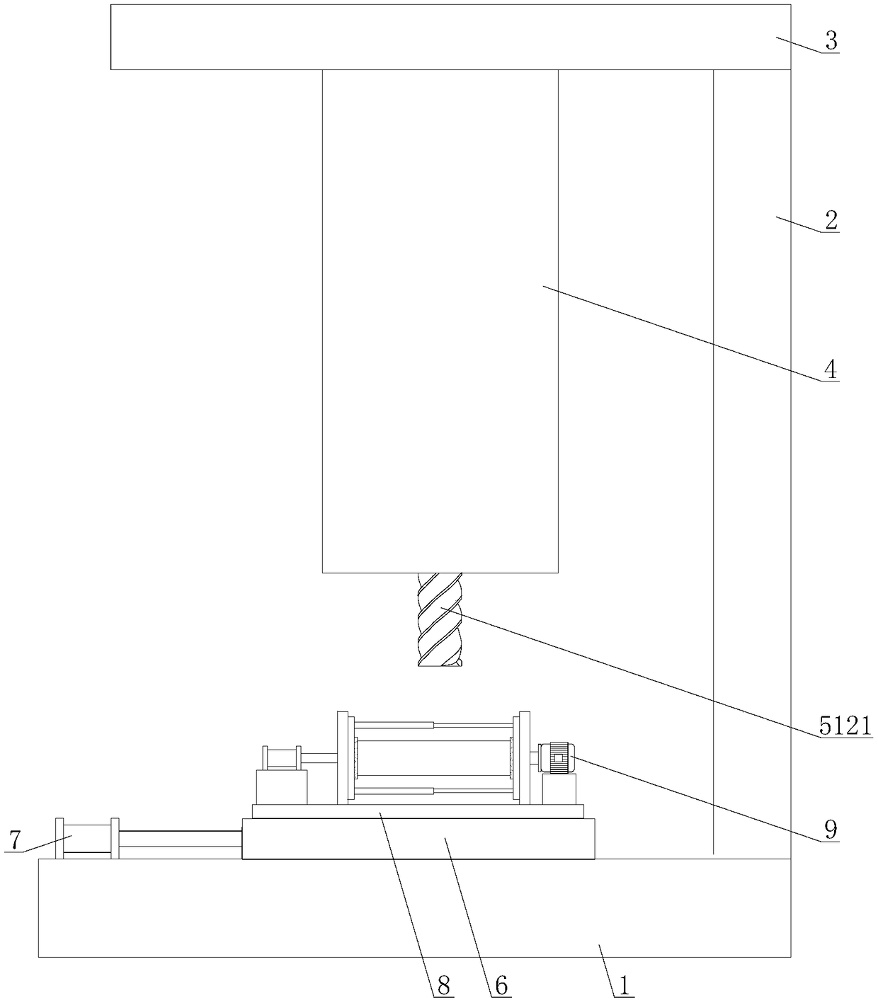
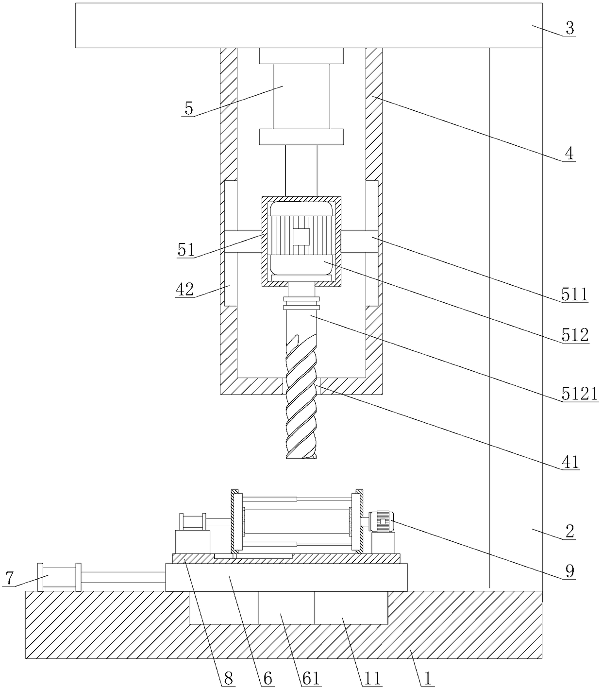
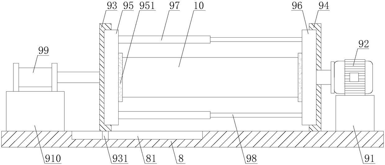
[0021] see Figure 1-2 , a milling device for ore processing, comprising a base 1, a first support vertical plate 2 is installed on the upper surface of one end of the base 1, a support horizontal plate 3 is installed on the top of the first support vertical plate 2, and the lower support horizontal plate 3 A U-shaped support frame 4 is installed on the surface, and a first cylinder 5 is arranged on the inside of the U-shaped support frame 4. The first cylinde...


PUM


Abstract

The invention belongs to the technical field of ore processing equipment, and discloses an ore processing milling device which comprises a base. A first support vertical plate is mounted on the uppersurface of the base, a support transverse plate is mounted on the top of the first support vertical plate, a U-shaped support frame is mounted on the lower surface of the support transverse plate, a first air cylinder is arranged on the inner side of the U-shaped support frame, a motor fixing seat is connected with a piston rod of the first air cylinder, a first motor is arranged on the inner sideof the motor fixing seat, and a milling cutter is connected with an output shaft of the first motor by couplings. The ore processing milling device has the advantages that a second motor can work when the end surfaces of the other side of ore need to be milled, accordingly, a first clamping block and a second clamping block can rotate, the ore further can synchronously rotate until the to-be-processed end surfaces of the other side of the ore rotate to reach locations below the milling cutter, the to-be-processed end surfaces of the other side of the ore can be milled by the milling cutter, users can replace different processed surfaces of the ore without detaching the ore, and the ore processing milling device is easy to operate, low in labor intensity and high in milling efficiency.

Description

technical field [0001] The invention relates to the technical field of ore processing, in particular to a milling device for ore processing. Background technique [0002] Milling is a high-efficiency machining method that uses a rotating multi-blade tool to cut a workpiece. When working, the tool rotates as the main movement, and the workpiece moves as the feed movement. The workpiece can also be fixed, but at this time the rotating tool must also move, that is, the main movement and the feed movement are completed at the same time. Milling is generally carried out on a milling machine or a boring machine. It is suitable for processing planes, grooves, various forming surfaces (such as splines, gears and threads) and special surfaces of molds, etc. [0003] When the existing ore is milled, most of the ore is fixed by the fixture, and then the milling cutter rotates as the main movement, and the ore moves as the feed movement, so that the milling cutter can mill the ore, the...

Claims


Application Information

Patent Timeline
Patent Type & Authority Applications(China)
IPC IPC(8): B28D1/18B28D7/04
CPCB28D1/18B28D7/04
Inventor 张胜黄方保
Owner 安徽捷运矿山机械有限公司
Why Eureka
Eureka Blog
Learn More