Multi-rotor aircraft

A multi-rotor aircraft and rotor technology, applied in the field of aircraft, can solve the problems of unbalanced flight efficiency and aircraft size, reduced flight efficiency, increased load, etc., to increase load and flight time, improve flight efficiency, reduce The effect of footprint

Inactive Publication Date: 2019-01-25
FOSHAN SHENFENG AVIATION SCI & TECH
View PDF0 Cites 1 Cited by
  • Summary
  • Abstract
  • Description
  • Claims
  • Application Information

AI Technical Summary

Problems solved by technology

[0003] At present, most of the multi-rotor aircraft are evenly distributed among the propellers, relying on the lift generated by the rotors to move, but the size is relatively large; while the design of the coaxial twin propellers has a small size, the flight efficiency is greatly reduced, and The load is increased, and the relationship between flight efficiency and aircraft size cannot be well balanced

Method used


Image

  • Multi-rotor aircraft
  • Multi-rotor aircraft
  • Multi-rotor aircraft

Examples


Embodiment 1

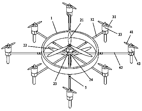
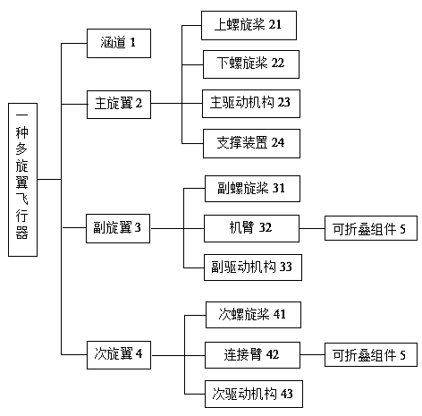
[0051] See attached figure 1 , the main rotor 2 is set inside the duct 1, the auxiliary rotor 3 and the secondary rotor 4 are located at the periphery of the duct 1, and the secondary rotor 4 is located at the periphery of the auxiliary rotor 3, the two are not on the same circumferential surface, so they are reduced to a certain extent The peripheral dimensions when the auxiliary propeller is unfolded, and the auxiliary propeller and the secondary propeller will not affect each other when they are in working condition at the same time; the main driving mechanism 23 of the main rotor 2 is a fuel engine, and the driving mechanisms of the auxiliary rotor 3 and the secondary rotor 4 are electric motors ,

[0052] That is, the main lift of the aircraft is provided by the main rotor 2 driven by the fuel engine, which can greatly increase the load and flight time of the aircraft; the auxiliary rotor 3 driven by the electric motor provides the attitude control moment of the aircraft,...

Embodiment 2

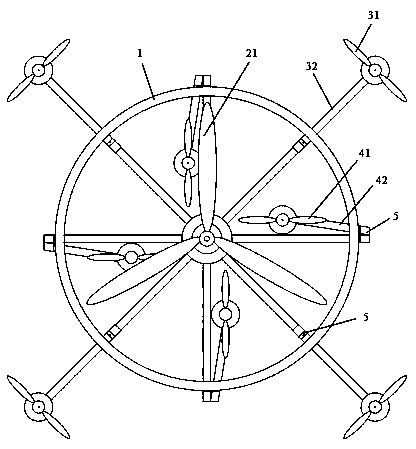
[0062] See attached figure 2 , the main rotor 2 is arranged inside the duct 1, and the auxiliary rotor 3 is located at the periphery of the duct 1; wherein the main driving mechanism 23 of the main rotor 2 is a fuel engine, and the auxiliary driving mechanism 33 of the auxiliary rotor 3 is an electric motor,

[0063] That is, the main lift of the aircraft is provided by the main rotor 2 driven by the fuel engine, which can greatly increase the load and flight time of the aircraft; the auxiliary rotor 3 driven by the electric motor provides the attitude control moment of the aircraft, controls the attitude of the aircraft, and assists the main rotor 2 Precisely adjust the lift. The lift of the aircraft is set to a coarse and fine two-level adjustment mechanism, which is conducive to improving the utilization rate of fuel and batteries, and is conducive to improving the accuracy of control.

[0064] The upper propeller 21 and the lower propeller 22 fixed to the top and the bott...


PUM


Abstract

The invention discloses a multi-rotor aircraft, comprising a duct, a main rotor and a plurality of auxiliary rotors. The main rotor is located on the inside of the duct, and the aileron is uniformly distributed on the periphery of the duct. The main rotor comprises an upper propeller, a lower propeller and a main driving mechanism coaxially arranged, wherein the main driving mechanism is located at a central position on the inner side of the duct, and the upper propeller and the lower propeller are respectively fixed to the top end and the bottom end of the main driving mechanism by a supporting device, and the rotational direction is opposite. The auxiliary rotor comprises an auxiliary propeller, an arm and an auxiliary drive mechanism. One end of the arm is connected with a support device, the other end of the arm is fixedly connected with the auxiliary drive mechanism, and the auxiliary propeller is mounted on the top end of the auxiliary drive mechanism. The invention discloses a multi-rotor aircraft with simple structure, which can adjust the size according to specific conditions and improve flight efficiency.

Description

technical field [0001] The present invention relates to the technical field of aircraft, and more specifically relates to a multi-rotor aircraft. Background technique [0002] Aircraft (flight vehicle) is an instrument flying object that is manufactured by humans, can fly off the ground, fly in space and is controlled by humans in the atmosphere or in space outside the atmosphere. Multi-rotor aircraft is also called multi-axis aircraft, which is a helicopter One, its maneuverability is achieved by changing the torque and speed of different rotors, and it is widely used in fields such as film and television aerial photography, security monitoring, agricultural plant protection, and power line inspection. [0003] At present, most of the multi-rotor aircraft are evenly distributed among the propellers, relying on the lift generated by the rotors to move, but the size is relatively large; while the design of the coaxial twin propellers has a small size, the flight efficiency is...

Claims


Application Information

Patent Timeline
Patent Type & Authority Applications(China)
IPC IPC(8): B64C27/08B64C27/10B64C27/14B64C3/56
CPCB64C27/08B64C3/56B64C27/10B64C27/14
Inventor 王志成肖凤兰
Owner FOSHAN SHENFENG AVIATION SCI & TECH
Why Eureka
Try Eureka