A landing support mechanism for a pneumatically deployable, retractable and repeatable carrier

A technology of support mechanism and support legs, applied in the field of repeated carrier landing support mechanism, can solve problems such as instability and failure of recovery work, and achieve the effects of high reliability, multiple use, and high landing stability

Active Publication Date: 2021-06-15
HARBIN INST OF TECH
View PDF5 Cites 0 Cited by
  • Summary
  • Abstract
  • Description
  • Claims
  • Application Information

AI Technical Summary

Problems solved by technology

[0005] The present invention solves the problem that the existing support mechanism used for the soft landing of the carrier may be in an unstable state due to the influence of the first-order vibration, resulting in the failure of the recovery work, and further provides a pneumatically deployed and folded repeat carrier landing support mechanism

Method used


Image

  • A landing support mechanism for a pneumatically deployable, retractable and repeatable carrier
  • A landing support mechanism for a pneumatically deployable, retractable and repeatable carrier
  • A landing support mechanism for a pneumatically deployable, retractable and repeatable carrier

Examples


specific Embodiment approach 1

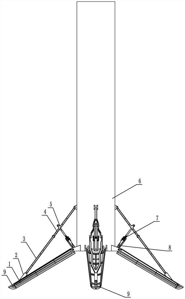
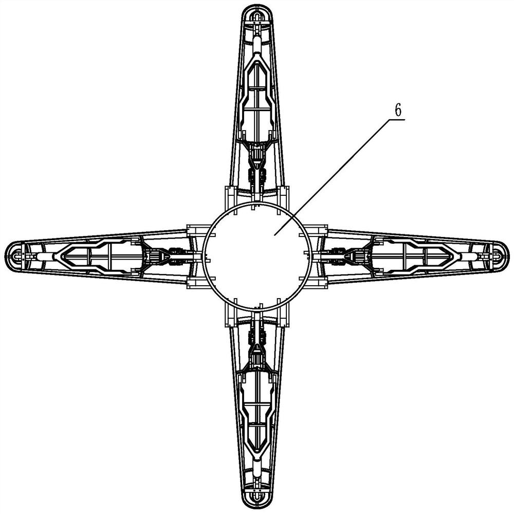
[0022] Specific implementation mode one: as figure 1 with figure 2 As shown, the pneumatic deployment, folding and repeating carrier landing support mechanism of this embodiment includes four sets of folding, locking, and buffering integrated mechanisms, and the four sets of folding, locking, and buffering integrated mechanisms are uniformly arranged on the lower part of the rocket body 6 along the circumferential direction. The integrated folding, locking and buffering mechanism includes the landing support leg 1, the hydraulic buffer 2, the buffer support link 3, the auxiliary support link 4, the cylinder drive link 5, the cylinder locking mechanism 7, the cylinder 8 and the foot pad 9 , the upper end of the landing support leg 1 is rotationally connected with the outer edge of the lower end of the rocket body 6, the lower end of the landing support leg 1 is provided with a foot pad 9, the hydraulic buffer 2 is installed on the lower part of the buffer support link 3, and t...

specific Embodiment approach 2

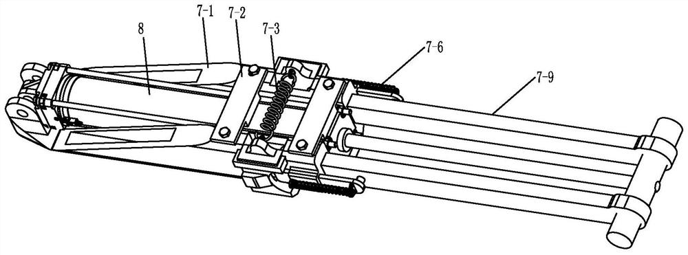
[0026] Specific implementation mode two: as image 3 , Figure 4 with Figure 5 As shown, the cylinder locking mechanism 7 in this embodiment includes a locking support seat 7-1, a locking driving spring 7-3, a locking slider 7-5, a limit driving spring 7-6, and two locking driving rods. 7-9 and two limit baffles 7-10; the cylinder 8 is installed on the locking support seat 7-1, the lower end of the cylinder 8 is rotationally connected with the locking support seat 7-1, and the two limit baffles 7-1 10 is arranged on the outside of two locking driving rods 7-9, and the described one end of cylinder driving connecting rod 5 is provided with connecting rod 7-8 perpendicular thereto, and one end of two locking driving rods 7-9 is connected with connecting rod 7 -8 rotating connection, the other ends of the two locking drive rods 7-9 can slide in the inner guide groove 7-1-1 of the locking support seat 7-1 and be limited by the end of the inner guide groove 7-1-1 The two sides ...

specific Embodiment approach 3

[0028] Specific implementation mode three: as image 3 with Figure 5 As shown, the cylinder locking mechanism 7 of this embodiment also includes a cylinder pressure plate 7-2 and a screw 7-4; the cylinder 8 is fixed through the cylinder pressure plate 7-2 and the screw 7-4 arranged on the locking support seat 7-1 On the locking support seat 7-1. Designed in this way, it is convenient to install the cylinder 8 and be installed on the locking support seat 7-1. Other components and connections are the same as those in the second embodiment.


PUM


Abstract

The utility model relates to a landing supporting mechanism of a pneumatically unfolding and retracting repetitive carrier, which relates to a landing supporting mechanism. The invention solves the problem that the existing support mechanism used for the soft landing of the carrier may be in an unstable state due to the influence of the first-order vibration, resulting in the failure of the recovery work. The upper end of the landing support leg is rotatably connected with the outer edge of the lower end of the rocket body, the hydraulic buffer is installed at the lower part of the buffer support link, the lower end of the buffer support link is rotatably connected with the foot pad, and the upper end of the buffer support link passes through the first A rotating shaft and a buffer bearing are rotatably connected to the lower end of the auxiliary support link, the upper end of the auxiliary support link is rotatably connected to the lower part of the rocket body, and the middle and lower part of the auxiliary support link is connected to one end of the cylinder drive link through a cylindrical pin, and the cylinder drives The other end of the connecting rod is connected with one end of the cylinder through the cylinder locking mechanism, and the other end of the cylinder is rotationally connected with the lower end of the rocket body. The invention is used for pneumatically deploying and retracting repeated carrier landing.

Description

technical field [0001] The invention relates to a landing support mechanism for a carrier, in particular to a landing support mechanism for a carrier that is deployed and folded repeatedly by pneumatic drive. Background technique [0002] At present, rockets are mainly used for one-time use. After the rocket mission is completed, it cannot be reused after it lands freely. However, the main components of the rocket are expensive and the fuel cost is relatively low. The resulting waste is a major factor hindering the rapid response of the rocket. Rocket recovery can greatly reduce launch costs. The support mechanism is a key technology in vertical take-off and landing carrier technology. The support legs and buffers in the support mechanism can achieve a soft landing of the vehicle, and it can be reused through subsequent maintenance and fuel replenishment. [0003] The existing support mechanism used for landing has a small support circle diameter and excessive air resistance...

Claims


Application Information

Patent Timeline
Patent Type & Authority Patents(China)
IPC IPC(8): B64G1/62
CPCB64G1/62
Inventor 高海波于海涛田保林刘振李楠丁亮邓宗全
Owner HARBIN INST OF TECH
Why Eureka
Try Eureka