Low hydration heat cement slurry

A technology with low hydration heat and hot water, applied in the field of cement slurry, can solve problems such as threats to workers and offshore drilling platforms, moderate deterioration of casing, instability of hydrate formations, etc. Avoid construction accidents and ensure the effect of integrity

Inactive Publication Date: 2019-01-25
CHINA NAT OFFSHORE OIL CORP +1
View PDF10 Cites 10 Cited by
  • Summary
  • Abstract
  • Description
  • Claims
  • Application Information

AI Technical Summary

Problems solved by technology

The decomposition of natural gas hydrate will lead to the instability of the hydrate formation and the collapse of the well wall; the diameter of the well will expand, the centering of the casing will deteriorate, and the cementing quality will decline; the decomposition will cause natural gas to enter the cement slurry system, which will directly cause the cement slurry to not solidify; It will also lead to pr

Method used


Image

  • Low hydration heat cement slurry
  • Low hydration heat cement slurry
  • Low hydration heat cement slurry

Examples


Example Embodiment

[0033] Example 1

[0034] The components are weighed according to the following proportions by mass:

[0035] Grade G oil well cement: 300 parts; low hydration heat cementitious material fly ash: 150 parts; low hydration heat cementitious material slag: 150 parts; water loss agent: 3 parts; dispersant: 1.2 parts; defoaming Agent: 0.5 part; slurry water: 300 parts.

[0036] Preparation method: dry-mix G-grade oil well cement, low-hydration thermal cementitious material fly ash and slag uniformly, mix the wet-mixing admixture with water uniformly, and then mix the obtained aqueous solution and powder according to API 10-3-2004 oil well Cement test methods for the preparation of cement slurries.

Example Embodiment

[0037] Example 2

[0038] The components are weighed according to the following proportions by mass:

[0039] Grade G oil well cement: 255 parts; low hydration heat cementitious material fly ash: 127.5 parts; low hydration heat cementitious material slag: 127.5 parts; solid low density reducing agent: 90 parts; water loss agent: 2 parts ; Dispersant: 4 parts; Defoamer: 0.5 part; Slurry water: 360 parts.

[0040] Preparation method: dry-mix G-grade oil well cement, low-hydration thermal cementitious material fly ash and slag, and low-density reducing agent uniformly, mix the wet-mixing admixture with water uniformly, and then mix the obtained aqueous solution and powder according to API 10 -3-2004 Oil Well Cement Test Method to prepare cement slurry.

Example Embodiment

[0041] Example 3

[0042] The components are weighed according to the following proportions by mass:

[0043] Grade G oil well cement: 232.5 parts; low hydration heat cementitious material fly ash: 116.5 parts; low hydration heat cementitious material slag: 116.5 parts; solid low density reducing agent: 135 parts; fluid loss agent: 2 parts ; Dispersant: 5.0 parts; Defoamer: 0.5 part; Slurry water: 360 parts.

[0044] Preparation method: dry-mix G-grade oil well cement, low-hydration thermal cementitious material fly ash and slag, and low-density reducing agent uniformly, mix the wet-mixing admixture with water uniformly, and then mix the obtained aqueous solution and powder according to API 10 -3-2004 Oil Well Cement Test Method to prepare cement slurry.


PUM


Abstract

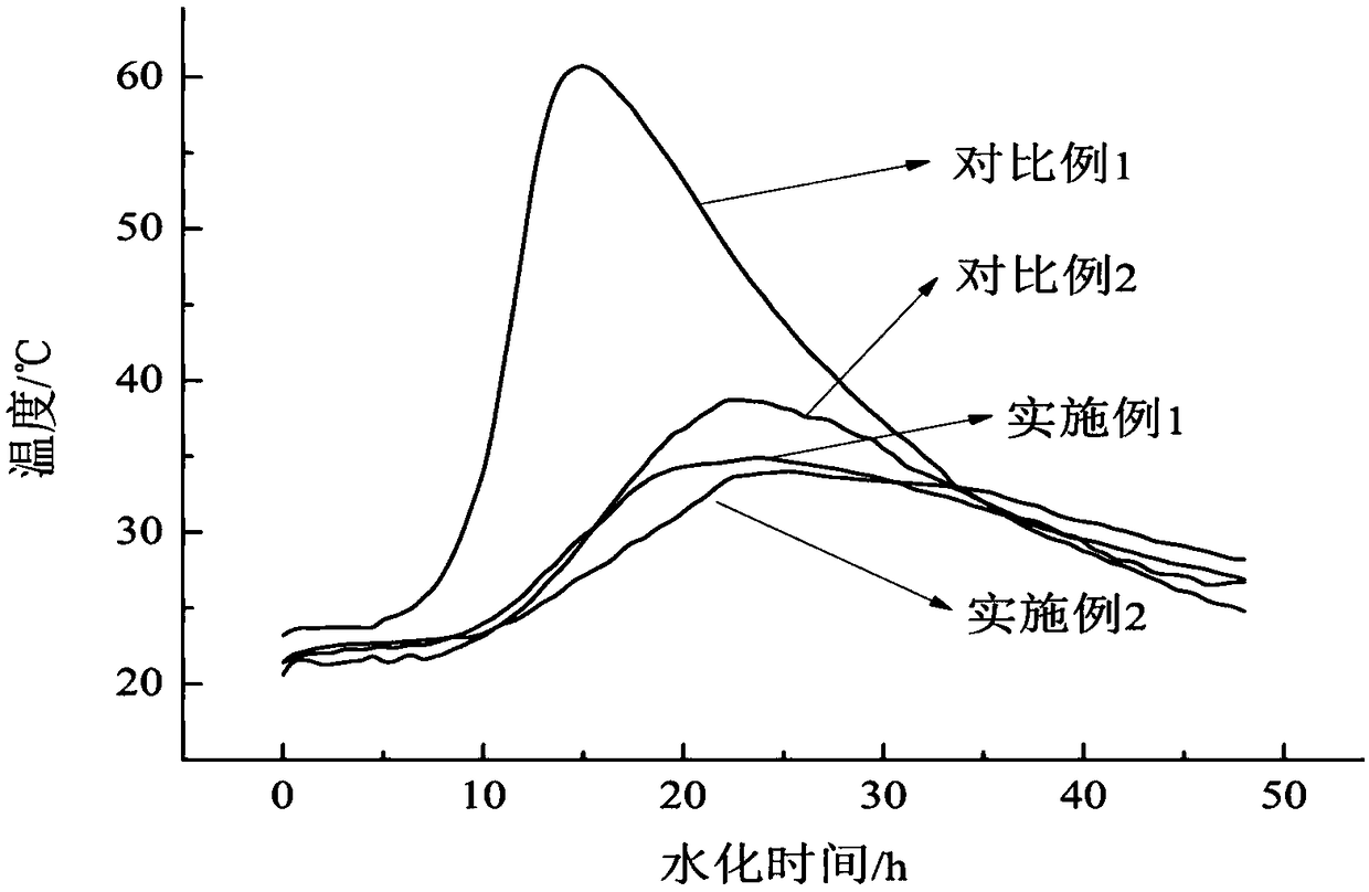
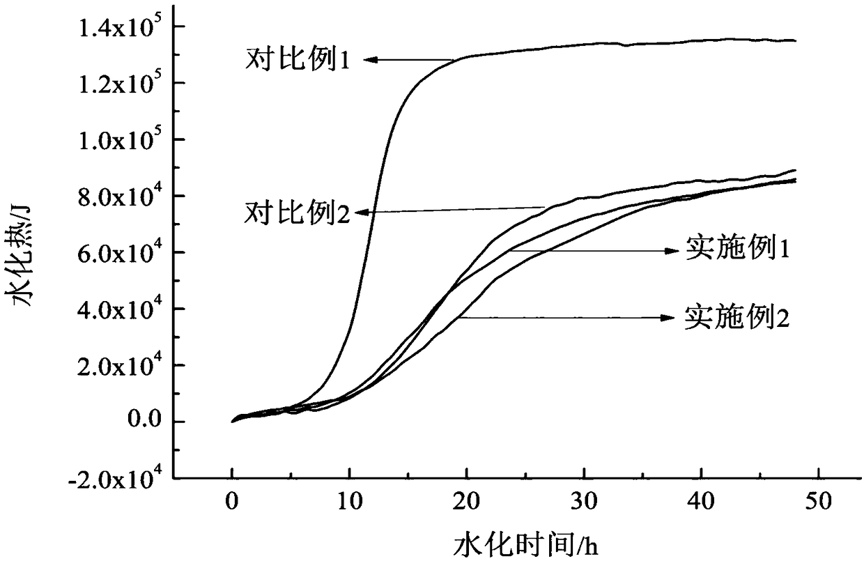
The invention discloses low hydration heat cement slurry which comprises, by weight parts, 232.5-300 parts of G grade oil well cement, 116.5-150 parts of low hydration thermal gelling material fly ash, 116.5-150 parts of low hydration thermal gelling material slag, 0-135 parts of solid low density reducing agent, 1-3 parts of fluid loss agent, 0.5-5 parts of dispersing agent, 0.5-2 parts of antifoaming agent and 300-360 parts of blended water. The hydration heat of the low hydration heat cement slurry is reduced obviously, and the hydration heat is as low as 50% that of a conventional cement slurry system, which greatly reduces the temperature of annulus cement slurry in the well cementation construction stage of waiting on cement setting and lowers the risk of deepwater natural gas hydrate stratum construction. The low hydration heat cement slurry has a low density and excellent density stability, avoiding a construction accident of natural gas hydrate formation leakage caused by density unstability of the cement slurry system.

Description

technical field [0001] The invention relates to a cement slurry, in particular to a cement slurry suitable for well cementing construction of a deep-water natural gas hydrate layer in the field of petroleum drilling engineering. Background technique [0002] With the increasing global demand for energy and the exhaustion of conventional oil and gas resources, the current exploration and development areas have gradually developed into deep water and ultra-deep water areas, and unconventional oil and gas resources have become the focus of people's attention. During the exploration and development of deepwater oil and gas resources, it is inevitable to encounter gas hydrate formations. Natural gas hydrate is a non-stoichiometric clathrate compound formed by liquid water and gaseous natural gas (the main component is methane) at low temperature and high pressure. This substance can burn when exposed to fire, so it is also called "combustible ice". , which widely exist in permaf...

Claims


Application Information

Patent Timeline
IPC IPC(8): C09K8/467C04B28/08
CPCC04B28/08C04B2111/00724C09K8/467C04B7/02C04B18/08C04B16/04C04B2103/46C04B24/24C04B24/42
Inventor 李中黄熠彭志刚郭永宾董星亮颜帮川杜威陈浩东刘和兴吴旭东邢希金霍锦华胡文军徐碧华罗东辉
Owner CHINA NAT OFFSHORE OIL CORP
Why Eureka
Try Eureka