Water diversion tunnel structure

A diversion tunnel and drainage tunnel technology, applied in water conservancy projects, hydropower, hydropower stations, etc., can solve problems such as steep and shallow slopes at the outlet of non-pressure diversion tunnels that cannot meet the submerged depth of water intakes, and difficult layout of diversion tunnels , to achieve the effect of avoiding unfavorable terrain and geological conditions, superior hydraulic conditions, and reducing the amount of seepage water

Pending Publication Date: 2019-01-25
CHINA POWER CONSRTUCTION GRP GUIYANG SURVEY & DESIGN INST CO LTD
View PDF0 Cites 3 Cited by
  • Summary
  • Abstract
  • Description
  • Claims
  • Application Information

AI Technical Summary

Problems solved by technology

In actual engineering application, limited by the overall layout of the hub or topographic and geological conditions, for example, there are deep downcut valleys along the water diversion line, and the steep exit slope of the non-pressure diversion tunnel makes it very difficult to excavate the forebay or the shallow water level of the reservoir is difficult. When the submerged depth of the water intake is satisfied, it is difficult to arrange the diversion tunnel as a single non-pressure tunnel or pressurized tunnel

Method used


Image

  • Water diversion tunnel structure
  • Water diversion tunnel structure
  • Water diversion tunnel structure

Examples


Embodiment Construction

[0030] The technical solution of the present invention is further described below, but the scope of protection is not limited to the description.

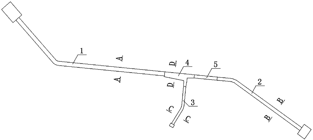
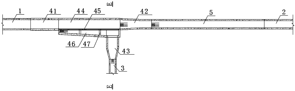
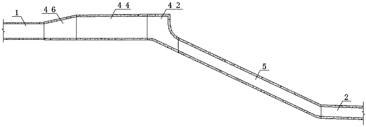
[0031] Such as Figure 1-8 As shown, a diversion tunnel structure includes a non-pressure tunnel 1, a pressure tunnel 2, and a drainage tunnel 3; , in order to meet the pressure water flow requirements of the hydropower station, the downstream of the regulating pool 4 is provided with an inclined well 5 to make the water flow transition from pressureless to pressurized. The surge well or the pressure steel pipe is connected; the regulating tank 4 includes an upstream transition section 41, a downstream transition section 42, a side transition section 43 and an intermediate section, one end of the middle section is connected with the upstream transition section 41, and the other end is connected with the downstream transition section 42 connection, one side of the middle section is connected with the side transition section 43; one...


PUM


Abstract

The invention provides a water diversion tunnel structure which comprises a pressure-free tunnel, a pressured tunnel and a drainage tunnel. The pressure-free tunnel is connected with the pressured tunnel through a regulating tank, the drainage tunnel is connected with the regulating tank, and an inclined shaft is arranged on the downstream of the regulating tank and connected with the pressured tunnel; the regulating tank comprises an upstream transition section, a downstream transition section, a side face transition section and a middle section, one end of the middle section is connected with the upstream transition section while the other end of the same is connected with the downstream transition section, and one side of the middle section is connected with the side face transition section; one end of the upstream transition section is smoothly connected with the tail end of the pressure-free tunnel, one end of the downstream transition section is smoothly connected with the inclined shaft, and one end of the side face transition section is smoothly connected with the head end of the drainage tunnel. A water diversion tunnel of a hydropower station is arranged to be a water diversion tunnel without pressure in the front and with pressure in the rear, and respective advantages of the pressured tunnel and the pressure-free tunnel in the aspects of engineering layout, hydraulic performance, stressed characteristic and running condition can be brought into full play.

Description

technical field [0001] The invention relates to a diversion tunnel structure, which belongs to the technical field of hydropower and water conservancy engineering, and is especially suitable for long-distance transmission projects where diversion-type hydropower stations are limited by unfavorable terrain and geological conditions or the comprehensive layout of hubs, and are difficult to design as a single unpressurized tunnel or pressurized tunnel. water tunnel. Background technique [0002] At present, domestic hydropower development is mostly concentrated in the southwest region. The river gradient is relatively large, the flow is relatively small, the valley is mostly narrow "V" shape, and the geological conditions are relatively complex. It is economically reasonable to build a diversion-type hydropower station with long-distance underground diversion tunnels. of. [0003] The diversion tunnel is a water delivery structure that leads the power generation water flow fro...

Claims


Application Information

Patent Timeline
Patent Type & Authority Applications(China)
IPC IPC(8): E02B9/02
CPCE02B9/02Y02E10/20
Inventor 文浩向贤镜严成斌陈琰杨曼
Owner CHINA POWER CONSRTUCTION GRP GUIYANG SURVEY & DESIGN INST CO LTD
Why Eureka
Try Eureka