
Composite steel sheet pile concrete diaphragm wall

A steel sheet pile and composite technology, applied in the direction of sheet pile wall, building, foundation structure engineering, etc., can solve the problem of not improving the waterproof and anti-corrosion ability of the ground connection wall and improving the self-skeleton of the ground connection wall Intensity, unable to enhance the strength of the ground connection wall itself, to achieve the effect of improving stability and waterproofing, improving waterproof ability, and preventing penetration

Active Publication Date: 2019-01-25
FOSHAN UNIVERSITY
View PDF5 Cites 0 Cited by
  • Summary
  • Abstract
  • Description
  • Claims
  • Application Information

AI Technical Summary

Problems solved by technology

[0004] Aiming at the deficiencies of the prior art, the present invention provides a ground connection wall of composite steel sheet piles, which solves the problem that the ground connection wall cannot be provided with a reliable connection method and the ground connection cannot be well enhanced. The waterproof and anti-corrosion capabilities of the wall cannot improve the strength of the ground wall's own skeleton, can't eliminate the cracks that occur when the ground wall is connected in sections, and can't prevent the external soil from interfering with the pouring density. Therefore, the problem that the self-strength of the ground connection wall cannot be well enhanced

Method used


Image

  • Composite steel sheet pile concrete diaphragm wall
  • Composite steel sheet pile concrete diaphragm wall
  • Composite steel sheet pile concrete diaphragm wall

Examples


Embodiment Construction

[0029] The following will clearly and completely describe the technical solutions in the embodiments of the present invention with reference to the accompanying drawings in the embodiments of the present invention. Obviously, the described embodiments are only some, not all, embodiments of the present invention.

[0030] In the description of the present invention, unless otherwise stated, the meaning of "plurality" is two or more; the terms "upper", "lower", "left", "right", "inner", "outer" , "front end", "rear end", "head", "tail", etc. indicate the orientation or positional relationship based on the orientation or positional relationship shown in the drawings, and are only for the convenience of describing the present invention and simplifying the description, rather than Nothing indicating or implying that a referenced device or element must have a particular orientation, be constructed, and operate in a particular orientation should therefore not be construed as limiting ...


PUM


Abstract

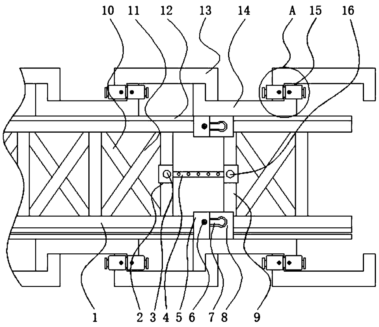
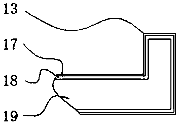
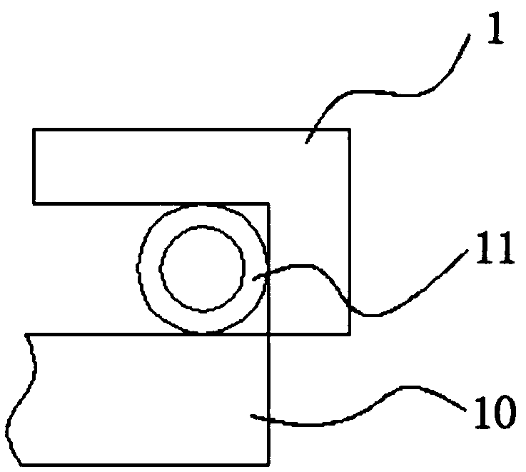
The invention discloses a composite steel sheet pile concrete diaphragm wall, and relates to the technical field of concrete diaphragm walls, in particular to a composite steel sheet pile concrete diaphragm wall. The composite steel sheet pile concrete diaphragm wall comprises a first reinforcing rod, a cross rod and a guiding rod, wherein the first reinforcing rod is welded to the cross rod; thecentral axis of the first reinforcing rod and the central axis of the cross rod are perpendicular to the guiding rod; a second reinforcing rod is mounted at the front end of the first reinforcing rod;angle bars are separately mounted on the upper side and the lower side of the second reinforcing rod; the second reinforcing rod is welded to the angle bars; a clamping block is mounted at the frontend of the cross rod; and the cross rod is positioned on the right side of the second reinforcing rod. According to the composite steel sheet pile concrete diaphragm wall, connection of concrete diaphragm walls is facilitated effectively by controlling the distance between the top end of the guiding rod and each angle bar, the concrete diaphragm walls with the lengths required for engineering arerapidly connected in the direction of the horizontal center line of the guiding rod by cooperation of a first fixing block, the guiding rod and a second fixing block, and thus, the concrete diaphragmwalls are matched with one another closely.

Description

technical field [0001] The invention relates to the technical field of ground connection walls, in particular to a ground connection wall of composite steel sheet piles. Background technique [0002] In recent years, the scale of urban underground space development has become larger and larger. The construction of subways, high-rise building basements, underground shopping malls, and comprehensive pipe corridors all require deep foundation pit engineering construction. Among them, the underground diaphragm wall can adapt to various geological conditions and is suitable for complex construction. Strong environmental adaptability, small impact on the environment during construction, good integrity, high safety, and good impermeability. It is considered to be one of the best retaining structures in deep foundation pit engineering. As a supporting structure, the underground diaphragm wall can Combined with the main structural wall, as the outer wall of the basement, it can reduc...

Claims


Application Information

Patent Timeline
IPC IPC(8): E02D5/04E02D5/08
CPCE02D5/04E02D5/08E02D2300/0029
Inventor 雷元新邓坚黄雅攀徐佳兴
Owner FOSHAN UNIVERSITY
Learn More