Safety box with automatic fire extinguishing function

A technology for safes and cabinets, which is applied in the field of safes, can solve the problems that safes enter the cabinet without any countermeasures, and cannot provide protection, so as to timely extinguish the fire, improve cost and applicability, The effect of good control

Inactive Publication Date: 2019-01-25
DEQING KEDITE COATING MACHINERY
View PDF8 Cites 7 Cited by
  • Summary
  • Abstract
  • Description
  • Claims
  • Application Information

AI Technical Summary

Problems solved by technology

[0007] In order to solve the problem that the existing safe does not have any countermeasures against fire or even fire in the cabinet, and almost has no protective effect at all, the present invention provides a self-extinguishing safe

Method used


Image

  • Safety box with automatic fire extinguishing function
  • Safety box with automatic fire extinguishing function
  • Safety box with automatic fire extinguishing function

Examples


Embodiment 1

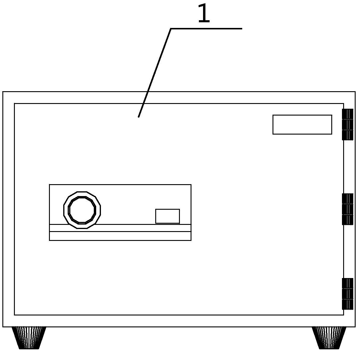
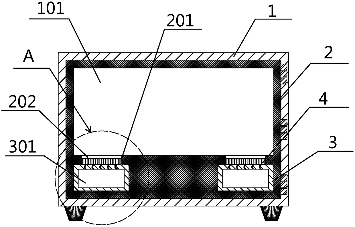
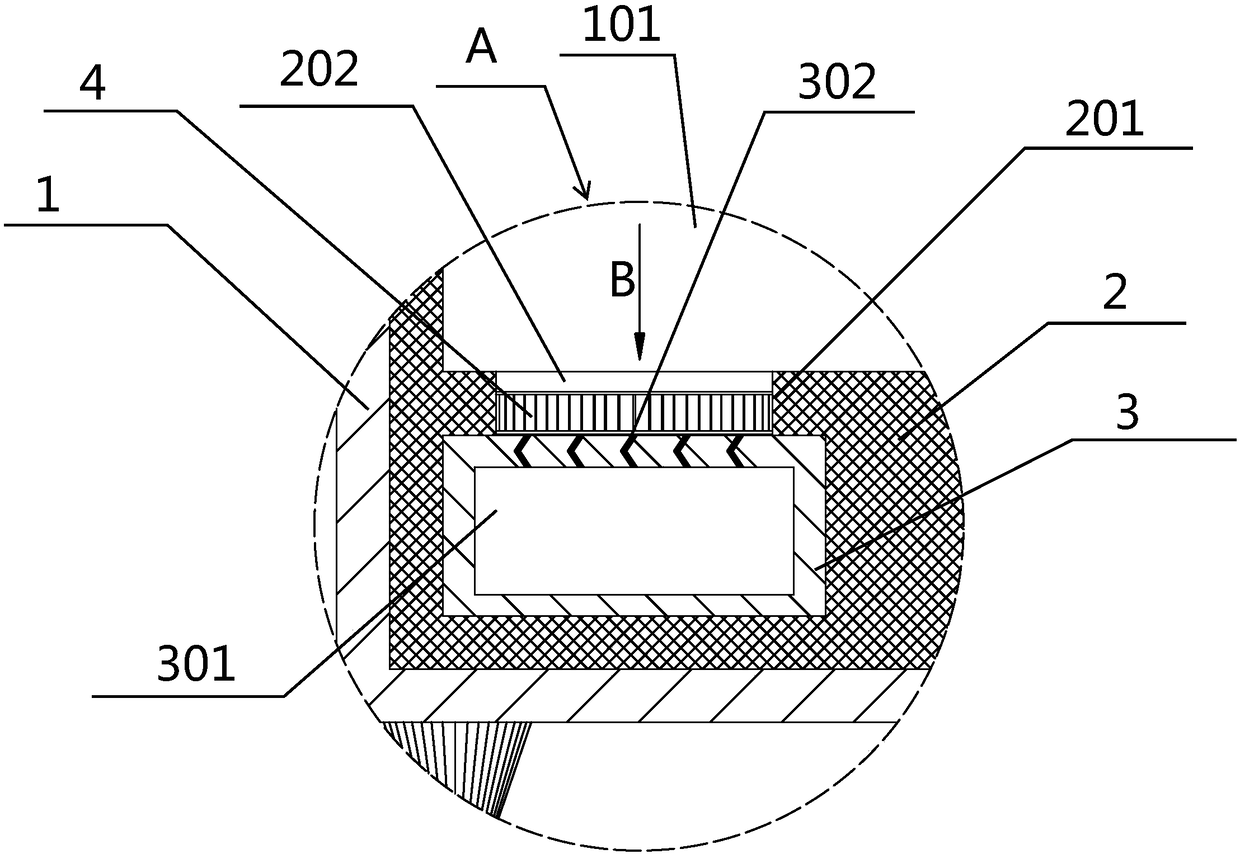
[0033] Such as figure 1 and figure 2 The shown self-extinguishing safe includes a main body 1 and a lining 2. The main body 1 includes a cabinet door, a cabinet body, a safety lock and cabinet feet. Cavity 101, the inner cavity 101 is used to store articles, and two liquid storage chambers 3 are also provided in the inner lining 2 of the bottom part of the cabinet body. The liquid storage chambers 3 have high compressive and flexural strength and have It is made of high-strength calcium silicate heat insulating material with good heat insulation performance. The liquid storage chamber 3 is a hollow structure, forming a liquid storage chamber 301. There is liquid carbon dioxide with a maximum capacity of about 4 / 5 in the liquid storage chamber 301, such as image 3 As shown, the upper end of the liquid storage chamber 3 is provided with several small through holes 302 filled with glass glue. The frictional force generated when the glass glue filled and blocked in the small t...

Embodiment 2

[0035] Such as figure 1 and figure 2 The shown self-extinguishing safe includes a main body 1 and a lining 2. The main body 1 includes a cabinet door, a cabinet body, a safety lock and cabinet feet. Cavity 101, the inner cavity 101 is used to store articles, and two liquid storage chambers 3 are also provided in the inner lining 2 of the bottom part of the cabinet body. The liquid storage chambers 3 have high compressive and flexural strength and have It is made of high-strength calcium silicate heat insulating material with good thermal insulation performance. The liquid storage chamber 3 is a hollow structure, forming a liquid storage chamber 301. There is liquid carbon dioxide with a maximum capacity of about 3 / 4 in the liquid storage chamber 301, such as image 3 As shown, the upper end of the liquid storage chamber 3 is provided with several small through-holes 302 filled with resin. The frictional force generated when the resin filled and blocked in the small through ...


PUM


Abstract

The invention relates to the technical field of safety boxes, provides a safety box with an automatic fire extinguishing function and aims to solve the problem that an existing safety box without anysolution for entering fire or breaking out fire has no protection function. The safety box with the automatic fire extinguishing function is provided to achieve two purposes: first of all, fire in thesafety box can be controlled and extinguished in time, and furtherly, safety of the safety box within a period of time after fire extinguishment can be guaranteed, fire can be prevented from enteringthe safety box again or sparks in the safety box can be prevented from reburning. The safety box comprises a main body and a liner, the main boxy comprises a box door, a box body, a safety lock and legs, the liner is arranged inside the main body and is arranged to form an inner cavity fitting with the box body, liquid storage rooms are arranged inside a bottom portion of the liner, liquid storage chambers are formed in the liquid storage rooms, a plurality of small through holes are formed in upper ends of the liquid storage rooms and filled with glass cement or resin, air holes formed in the bottom portion of the liner are correspondingly formed above the liquid storage rooms, the small through holes are formed in the air holes, and the small through holes are communicated with the inner cavity through the air holes.

Description

technical field [0001] The invention relates to the technical field of safes, in particular to a self-extinguishing fire safe. Background technique [0002] A safe (box) is a special container whose history can be traced back to the Middle Ages. In medieval paintings, you can occasionally see a wooden cabinet containing gold, silver and jewelry, which is the prototype of a modern safe. In the late 1850s, the lock industry was still underdeveloped. Although the appearance of safes at that time was changing with each passing day, the precision and reliability of the locks did not have much development. In the late 1860s, Americans invented the lock mechanism and multi-bolt technology for safes, and the safety performance of safes was greatly improved. In the 1960s and 1970s, due to the rapid development of semiconductor technology, the industry developed electronic combination locks, which are also widely used in various types of safe products. Later, LED and LCD digital di...

Claims


Application Information

Patent Timeline
Patent Type & Authority Applications(China)
IPC IPC(8): E05G1/12E05G1/02
CPCE05G1/02E05G1/12
Inventor 陈显忠
Owner DEQING KEDITE COATING MACHINERY
Why Eureka
Try Eureka